Material layer structure of blast furnace

A material layer structure and blast furnace technology, applied in blast furnaces, blast furnace details, furnaces, etc., can solve the problems of reducing production costs, iron-free iron content, coke consumption, etc., and achieve the effect of avoiding waste of energy

Inactive Publication Date: 2014-06-25
JIGANG GRP
View PDF10 Cites 3 Cited by
  • Summary
  • Abstract
  • Description
  • Claims
  • Application Information

AI Technical Summary

Problems solved by technology

When some abnormal conditions such as "bonding" occur in the furnace, the conventional method is to add some fluorite or manganese ore as a cleaning agent to the existing mixed ore layer to deal with the "bonding" p

Method used


Image

  • Material layer structure of blast furnace

Examples


specific Embodiment approach

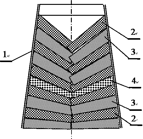
[0019] Specific implementation: such as figure 1 As shown, a blast furnace material layer structure includes mineral material and coke filled on the upper part of the blast furnace shaft 1, and the mineral material and coke are separately filled to form a mixed mineral layer 3 and a coke layer 2. The coke layer 2 and the mixed ore layer 3 are arranged at intervals and cyclically reciprocate. A single pellet ore layer 4 is also provided between the coke layer 2 and the mixed ore layer 3. The single pellet ore layer 4 can be added to the new material layer structure as a component of the entire material layer structure, and the single pellet ore layer 4 can be used as a replacement for the mixed ore layer 3.

[0020] In addition, because the high-temperature zone of the blast furnace is in the lower part, the high-temperature melting reaction occurs in the lower part of the blast furnace body. Therefore, the ore on the upper part of the blast furnace body is still "lumpy". It can b...


PUM


Abstract

The invention relates to a material layer structure in an iron-making blast furnace and particularly relates to a single pellet layer included material layer structure of a blast furnace. The material layer structure comprises mineral aggregates and cokes filled in the upper part of a blast furnace body, wherein the mineral aggregates and the cokes are respectively and independently filled to form mixing mineral layers and coke layers; the mixing mineral layers and the coke layers are arranged at intervals and are circularly overlaid; the thickness of each layer in the material layers of the blast furnace is the thickness of the material layer, which is lower than the material layer on the periphery of the round cavity, at the central position of a round cavity in the blast furnace; the material level is of a funnel shape with a downward cone angle; the pellet layers are also arranged between the coke layers and the mixing mineral layers and can be added into an overall material layer structure as a material layer constituent part of the overall material layer structure. By using the material layer structure with the 'single pellet layers', sticking substances in the furnace can be washed in time and the blast furnace can stably run for a long period of time in low cost.

Description

technical field [0001] The invention relates to a material layer structure in an iron-making blast furnace, in particular to a blast furnace material layer structure containing a single pellet layer. Background technique [0002] The blast furnace used for ironmaking in the metallurgical industry is a continuous cylindrical smelting equipment. The charge needs to be continuously loaded from the top of the blast furnace, and the hot air needs to be continuously blown in from the tuyeres at the lower part of the blast furnace. The molten iron is discharged from the taphole at the lower part of the blast furnace. Therefore, to ensure the continuity and stability of blast furnace production, we must first do in-depth and meticulous work on the charge of the blast furnace, including the stability of various physical and chemical indicators of the charge, the stability of the proportion structure of the charge, and the stability of the layer structure. Since the stability of the ...

Claims


Application Information

Patent Timeline
IPC IPC(8): C21B5/02
Inventor 曲建华位连增刘德楼高新运
Owner JIGANG GRP
Why Eureka
Try Eureka