Double-action type hydraulic transmission Stirling engine taking heat storage device as heat source

A Stirling engine and hydraulic transmission technology, which is applied in the direction of machines/engines, hot gas variable displacement engine devices, mechanical equipment, etc., can solve the problems of high failure rate of complex systems, limited use of secondary batteries, low voltage of single batteries, etc. problems, to achieve the effect of wide adaptability, low cost and reliable work

Inactive Publication Date: 2014-06-25
CHENGDU UNI LINK ENERGY
View PDF5 Cites 9 Cited by
  • Summary
  • Abstract
  • Description
  • Claims
  • Application Information

AI Technical Summary

Problems solved by technology

Internal combustion engines need to consume conventional fossil energy such as oil or natural gas, which not only has limited resources but also causes great pollution
Places that do not allow pollutant discharge mainly use electric motors as power, relying on power transmitted by the grid to work, and places where the grid cannot be used often use secondary batteries as power sources, and secondary batteries store and release electrical energy by electrochemical reactions. There will be pollutants discharged, and it is cleaner and more environmentally friendly than internal combustion engines. It has been widely developed and used, but batteries also have problems such as low voltage of single cells, limited cycle life, low operating efficiency under low temperature conditions, and high failure rate of complex systems. Limits the use of secondary batteries

Method used


Image

  • Double-action type hydraulic transmission Stirling engine taking heat storage device as heat source
  • Double-action type hydraulic transmission Stirling engine taking heat storage device as heat source
  • Double-action type hydraulic transmission Stirling engine taking heat storage device as heat source

Examples


Embodiment 1

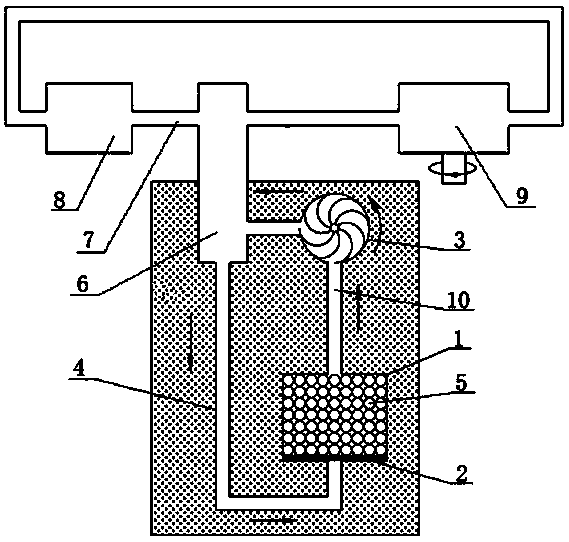
[0032] Such as figure 1 As shown, a double-acting hydraulic transmission Stirling engine with a heat accumulator as a heat source, which includes a heat accumulator shell 1, a heating element 2, a heat exchange system 3, an air inlet pipe 4, a heat storage body 5, a hydraulic pressure Transmission Stirling engine 6, hydraulic pipeline 7, hydraulic system liquid storage tank 8, hydraulic motor 9 and hot air pipeline 10, heat storage body 5 is a ceramic heat storage ball, located in the heater shell 1, and the heating element 2 is located in the heater Inside the shell 1 and in contact with the ceramic heat storage ball, the hot air pipe 10 communicates with the cold chamber of the hydraulic transmission Stirling engine 6 and the heater shell 1 through the heat exchange system 3. The heat exchange system 3 is a high-temperature hot air system, and the air inlet pipe 1 communicates with The thermal cavity of the hydraulic transmission Stirling engine 6 and the heater shell 1, th...

Embodiment 2

[0041] Such as figure 1 As shown, a double-acting hydraulic transmission Stirling engine with a heat accumulator as a heat source is characterized in that it includes a heat accumulator shell 1, a heating element 2, a heat exchange system 3, an air inlet duct 4, a heat storage Body 5, hydraulic transmission Stirling engine 6, hydraulic pipeline 7, hydraulic system liquid storage tank 8, hydraulic motor 9 and hot air pipeline 10, heat storage body 5 is ceramic heat storage ball, located in heater shell 1, heating element 2 is located in the heater shell 1 and is in contact with the ceramic heat storage ball. The hot air pipe 10 communicates with the cold chamber of the hydraulic transmission Stirling engine 6 and the heater shell 1 through the heat exchange system 3. The heat exchange system 3 is a high-temperature hot air system. The air duct 1 communicates with the hot chamber of the hydraulic transmission Stirling engine 6 and the heater shell 1, and the hydraulic Stirling ...


PUM


Abstract

The invention discloses a double-action type hydraulic transmission Stirling engine taking a heat storage device as a heat source. The engine comprises a heat storage device outer shell (1), a heating element (2), a heat exchange system (3), an air inlet pipeline (4), a heat storage body (5), a hydraulic transmission Stirling engine body (6), a hydraulic pipeline (7), a hydraulic system liquid storage tank (8), a hydraulic motor (9) and a hot air pipeline (10), and the hydraulic transmission Stirling engine body (6) is a double-action type engine body. The double-action type hydraulic transmission Stirling engine has the advantages of being low in cost, high in reliability, high in energy density, long in service life, little in maintenance, capable of being movably used, environmentally friendly and capable of using various kinds of energy.

Description

[0001] The present invention is a dual -function hydraulic transmission Stirling engine with a heat storage device as a heat source. It is "the application number 2011103809635, the application date of November 25, 2011, the invention name is a heat storage device as the heat source as the heat sourceSubstitute application for hydraulic transmission Sterling engine. Technical field [0002] The invention involved the Stirling engine, which specifically involved a dual -action hydraulic transmission from the heat storage device as the heat source. Background technique [0003] Energy issues are a high concern to the whole society.Most of the power devices currently used are internal combustion engines as power devices.Internal combustion engines need to consume conventional fossil energy such as petroleum or natural gas, which is not only limited but also very polluted.Places that are not allowed to discharge pollutants are mainly used as power. The power work transmitted by the gr...

Claims


Application Information

Patent Timeline
Patent Type & Authority Applications(China)
IPC IPC(8): F02G1/043F02G1/053
Inventor 毛珂况钧耀彭滔毛林彬
Owner CHENGDU UNI LINK ENERGY
Why Eureka
Try Eureka