Mechanical coupling type magnetic suspension wind turbine generator yaw system

A yaw system and coupling technology, applied in the field of mechanically coupled magnetic levitation fan yaw system, can solve the problems of limiting wind energy utilization, restricting the development of large-scale wind power, increasing wind power costs, etc., and eliminating the problem of low yaw control accuracy , The effect of reducing the yaw power consumption of the fan and reducing the energy conversion link

Active Publication Date: 2014-06-25
QUFU NORMAL UNIV +1
View PDF5 Cites 21 Cited by
  • Summary
  • Abstract
  • Description
  • Claims
  • Application Information

AI Technical Summary

Problems solved by technology

At present, large and medium-sized wind power yaw systems are generally driven by multiple motors, which has high yaw power consumption and high failure rate, which restricts the development of large-scale wind power, especially offshore wind power. The reason is that the installation and maintenance of offshore wind power requires large ships and Helicopter assistance, high yaw failure rate leads to higher wind power costs
Invention patent 200910161406.7 discloses a magnetic levitation yaw device, which uses magnetic levitation drive technology to greatly reduce the yaw fail...

Method used


Image

  • Mechanical coupling type magnetic suspension wind turbine generator yaw system
  • Mechanical coupling type magnetic suspension wind turbine generator yaw system
  • Mechanical coupling type magnetic suspension wind turbine generator yaw system

Examples


Embodiment Construction

[0015] The present invention will be further described below in conjunction with the accompanying drawings and embodiments.

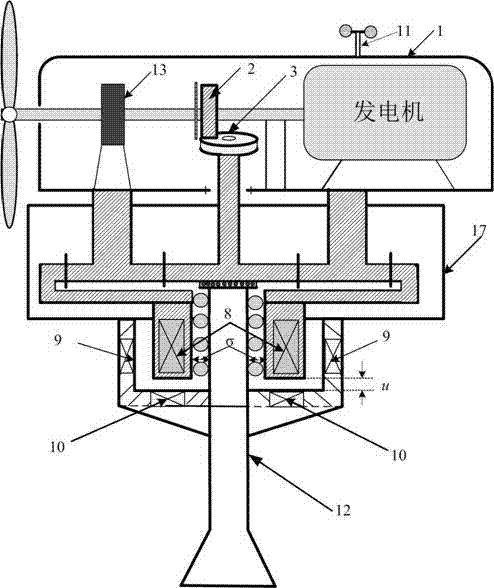
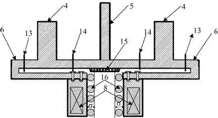
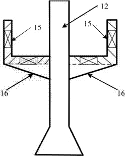
[0016] Such as figure 1 , figure 2 and image 3 As shown, the mechanically coupled maglev yaw system disclosed in the present invention includes a tower structure ( image 3 , horizontal suspension bracket 16, vertical suspension bracket 15 and tower 12), nacelle 1, planetary gear 17 (composed of sun gear 5, planetary carrier 4 and ring gear 6), mechanical coupling structure (composed of electromagnetic clutch 2 and bevel gear 3 ), a magnetic levitation mechanism composed of a vertical suspension winding 9 and a horizontal suspension winding 10 installed on the tower, and a stator winding 8 installed on the planetary gear ring gear 6.

[0017] Such as Figure 4 As shown, the control scheme of the mechanically coupled maglev yaw system disclosed in the present invention. The wind power generation system is a mature technology and is not protected by...


PUM


Abstract

The invention discloses a mechanical coupling type magnetic suspension wind turbine generator yaw system which is applied to a large and medium wind turbine generator. The mechanical coupling type magnetic suspension wind turbine generator yaw system comprises a planet gear, a conical gear, an electromagnetic clutch, vertical suspension windings, horizontal suspension windings and yaw motors. Wind turbine generator yaw mechanical torque and yaw motor torque are coupled through planet gear torque to drive a wind turbine generator cabin to be yawed. The wind turbine generator yaw mechanical torque is taken from electric generator front side wind turbine generator torque through the electromagnetic clutch and the conical gear with the fixed transformation ratio. The yaw motor torque is controlled by a bidirectional PWM converter during cabin suspension, cabin suspension is jointly controlled by the horizontal suspension windings and the vertical suspension windings, the cabin gravity is balanced through the horizontal suspension windings, the vertical suspension windings restrain off-centering, the yaw motors can work in the two modes including the electric mode and the regenerative braking mode through changes of the wind turbine generator yaw torque, and bidirectional energy flowing is completed through the PWM converter. According to the mechanical coupling type magnetic suspension wind turbine generator yaw system, the yaw power energy conversion link is omitted, the yaw power consumption is greatly reduced, and the wind energy use rate is improved.

Description

technical field [0001] The invention relates to a yaw system of a mechanically coupled magnetic levitation wind turbine, in particular to a yaw system applied to large and medium-sized wind power systems to realize accurate wind-facing of a nacelle. Background technique [0002] The yaw system of the wind turbine can make the wind turbine always face the wind, improve the utilization rate of wind energy of the wind turbine, and play a key role in ensuring the safe and stable operation of the wind turbine. At present, large and medium-sized wind power yaw systems are generally driven by multiple motors, which has high yaw power consumption and high failure rate, which restricts the development of large-scale wind power, especially offshore wind power. The reason is that the installation and maintenance of offshore wind power requires large ships and Assisted by helicopters, the high yaw failure rate leads to higher wind power costs. Invention patent 200910161406.7 discloses ...

Claims


Application Information

Patent Timeline
IPC IPC(8): F03D7/00F03D9/00F03D11/00
CPCY02E10/72
Inventor 褚晓广蔡彬孔英丁文龙
Owner QUFU NORMAL UNIV
Why Eureka
Try Eureka