Self-compensating vacuum valve

A vacuum valve, self-compensation technology, applied in the direction of valve lift, valve details, valve device, etc., can solve the problems of valve core and valve seat wall thickness thinning, vacuum valve leakage, poor sealing, etc., to achieve good guiding effect, prolong Service life, effect of achieving wear resistance

Pending Publication Date: 2017-12-12
郴州万墨环保科技有限公司
View PDF6 Cites 1 Cited by
  • Summary
  • Abstract
  • Description
  • Claims
  • Application Information

AI Technical Summary

Problems solved by technology

[0003] Vacuum valves in the prior art are generally suitable for conventional vacuum environments, and the range of operating pressure and operating temperature is small. Because the ambient temperature is not high, the valve closing parts of vacuum valves are sealed with rubber sealing rings or metal sealing rings, and the temperature resistance is not good. powerful
[0004] Even though there are vacuum valves with high temperature resistance on the market and the application of rubber sealing rings is abandoned, the relative parallel movement between the valve core and the valve seat forms a rigid opening and closing collision, which easily causes relative

Method used


Image

  • Self-compensating vacuum valve

Examples


Embodiment Construction

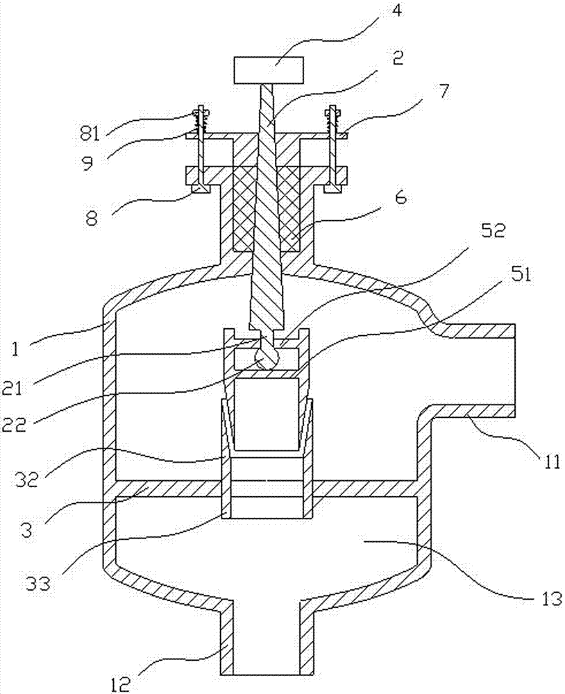
[0040] The present invention will be further described below in combination with specific embodiments. Wherein, the accompanying drawings are only for illustrative purposes, showing only schematic diagrams, rather than physical drawings, and should not be construed as limitations on this patent; in order to better illustrate the embodiments of the present invention, some parts of the accompanying drawings will be omitted, Enlargement or reduction does not represent the size of the actual product; for those skilled in the art, it is understandable that certain known structures and their descriptions in the drawings may be omitted.

[0041] Such as figure 1 As shown, a self-compensating vacuum valve includes a valve body 1 with an air inlet 11 and an air outlet 12, a valve stem 2, a valve seat 3 arranged in the inner cavity 13 of the valve body, and connected to one end of the valve stem 2 arranged outside the valve body. The flow regulating mechanism 4 and the valve core 5 whi...


PUM


Abstract

The invention belongs to the technical field of valves, and discloses a self-compensating vacuum valve. The self-compensating vacuum valve comprises a valve body, a valve rod, a valve seat, a flow rate adjusting mechanism and a valve element, wherein the valve body is provided with an air inlet and an air outlet; the valve seat is arranged in an inner cavity of the valve body; the flow rate adjusting mechanism is arranged at the outside of the valve body and is connected to one end of the valve rod; the valve element is arranged in the valve body and is in match with the other end of the valve rod; the valve seat is in sealing connection with the wall of the inner cavity of the valve body; a valve hole is formed in the center of the valve seat; the valve element is a circular platform of which one end is provided with a taper; a guide groove which protrudes from the surface of the valve seat and fits the taper of the valve element is formed in the valve hole; a valve column provided with a concave groove is arranged at a part where the outside of the valve body is in contact with the valve rod; the concave groove is filled with a flexible filler; a pressing plate which is connected to the valve column in a force balancing manner is arranged o the valve rod; the first surface of the pressing plate fits the concave groove, and the second surface of the pressing plate is provided with locking structures which are used for connecting the pressing plate and the valve column; the pressing plate is elastically connected to the locking structures. According to the vacuum valve, the valve element is automatically centered, and the valve rod is extruded by the filler to downwards move, so as to automatically compensate the abrasion loss of the valve element and the guide groove, thus the abrasion resistance of the vacuum valve is improved, and the service life is prolonged.

Description

technical field [0001] The invention relates to the technical field of valves, in particular to a self-compensating vacuum valve used in the metal smelting industry. Background technique [0002] Vacuum valve refers to the vacuum element used to isolate (cut off) the air flow, adjust the air flow, and distribute the air flow in the vacuum system. The air flow adjustment is realized through the opening and closing between the valve core and the valve seat. It is widely used because of its high air-tight reliability, small resistance to airflow, and flexible operation. [0003] Vacuum valves in the prior art are generally suitable for conventional vacuum environments, and the range of operating pressure and operating temperature is small. Because the ambient temperature is not high, the valve closing parts of vacuum valves are sealed with rubber sealing rings or metal sealing rings, and the temperature resistance is not good. powerful. [0004] Even though there are vacuum v...

Claims


Application Information

Patent Timeline
IPC IPC(8): F16K1/38F16K1/48F16K41/02
CPCF16K1/385F16K1/485F16K41/02
Inventor 王振华
Owner 郴州万墨环保科技有限公司
Why Eureka
Try Eureka