Wind-driven magnetic suspension flywheel assisted power generation system

An auxiliary power generation and magnetic levitation technology, which is applied in wind power generation, wind turbines, wind turbine combinations, etc., can solve the problems of affecting the service life of the generator, the mechanical impact of the generator shaft, and the insufficient utilization of wind energy, so as to reduce the yaw power consumption. , Reduce mechanical impact, improve the effect of wind energy utilization space

Pending Publication Date: 2019-04-23
QUFU NORMAL UNIV
View PDF2 Cites 16 Cited by
  • Summary
  • Abstract
  • Description
  • Claims
  • Application Information

AI Technical Summary

Problems solved by technology

However, the blades of large and medium-sized wind turbines work on 80-meter-high towers, and the wind speed and direction are relatively stable. The yaw of the nacelle only accounts for less than 30% of the total operating time of the wind turbine, and the maglev yaw device runs about 70% of the time at idle. In addition, when the power captured by the fan blades often exceeds the rated power of the generator, in order to protect the safety of the generator, the sidewind protection is often used, so that the wind energy cannot be fully utilized. At the same time, due to the problem of yaw power consumption, the utilization of wind energy is greatly reduced. Fluctuating wind speed can easily lead to mechanical impact on the generator shaft, seriously affecting the service life of the generator

Method used


Image

  • Wind-driven magnetic suspension flywheel assisted power generation system
  • Wind-driven magnetic suspension flywheel assisted power generation system
  • Wind-driven magnetic suspension flywheel assisted power generation system

Examples


Embodiment Construction

[0028] The present invention will be further described below in conjunction with accompanying drawings and examples.

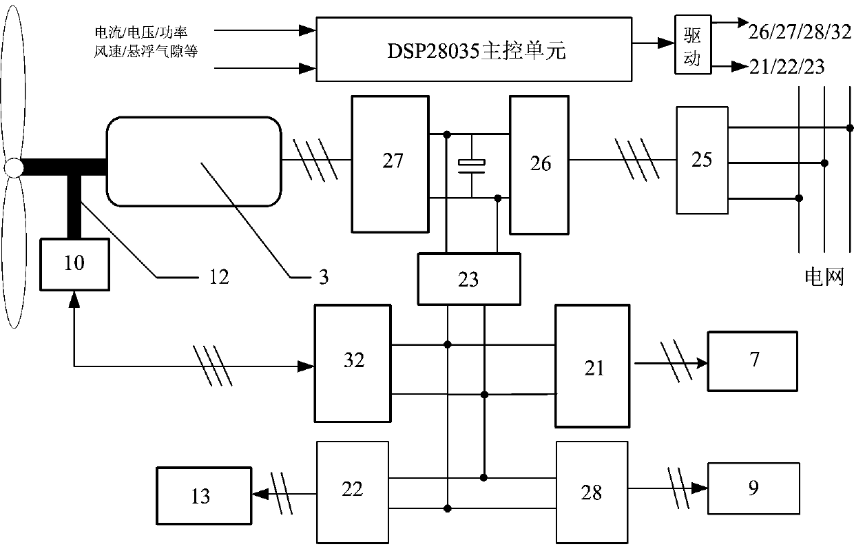
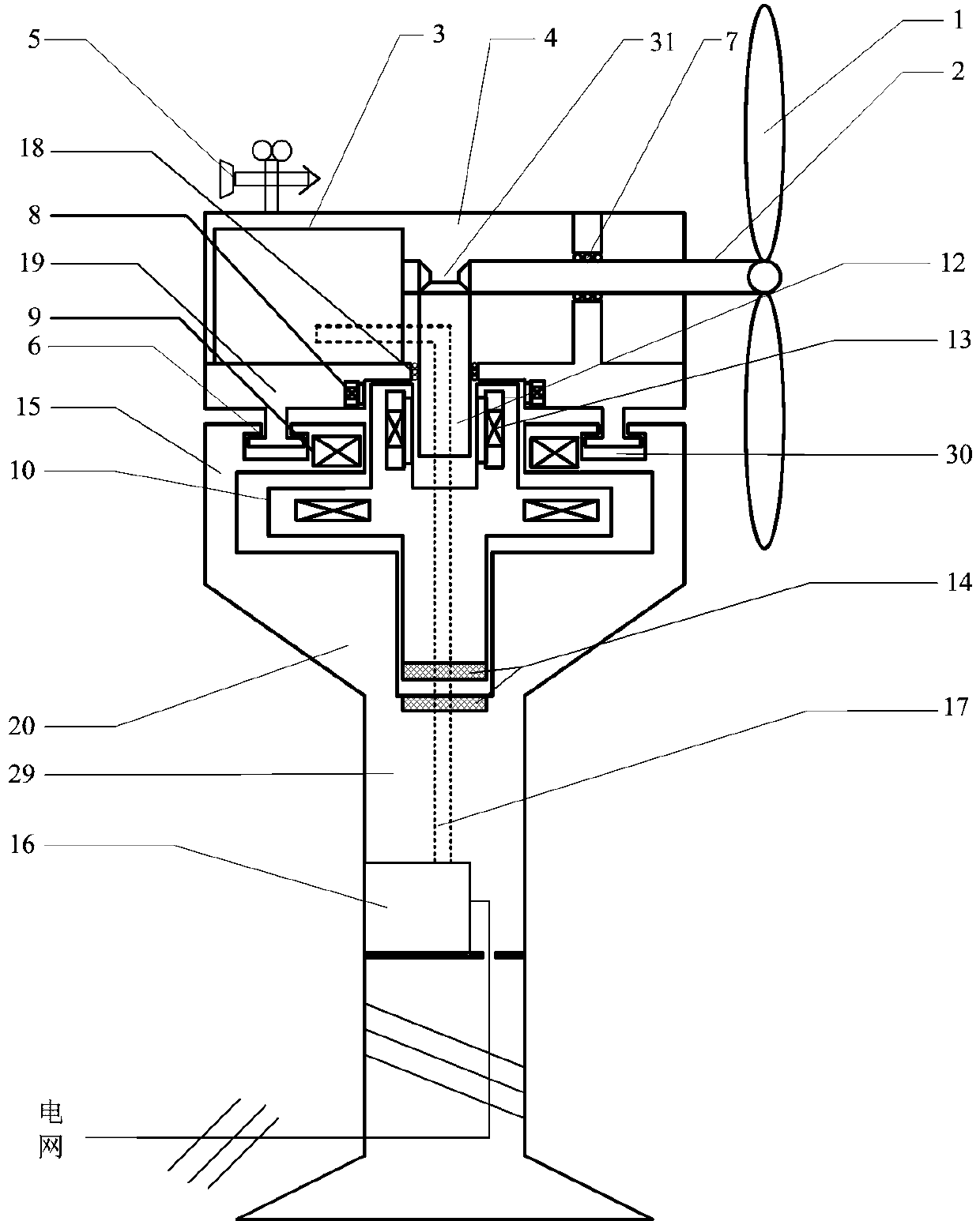
[0029] The wind-force maglev flywheel auxiliary power generation system disclosed in the present invention includes a nacelle 4, a generator 3, a nacelle rotating body 19, a flywheel rotating body 10, a flywheel yaw winding 11, a wind turbine limit bearing 7, a flywheel suspension winding 9, and a hybrid tower 20 (nacelle support 15 and tower bottom support 29), and the converter unit 16, cooperate to complete horizontal axis wind power generation, horizontal axis nacelle yaw and flywheel auxiliary energy storage; The electrical control part of the system, including machine side converter 27, grid side converter 26, step-up transformer 25, BUCK-BOOST converter 23, flywheel energy storage converter 32, flywheel suspension converter 21, flywheel lock The storage converter 22, the suspension damping converter 28, and the DSP28035 main control unit cooperate to co...


PUM


Abstract

The invention discloses a wind-driven magnetic suspension flywheel assisted power generation system. A magnetic suspension flywheel rotating body is adopted, upwind yaw and mechanical shock stabilization are implemented, a portion exceeding the rated power of a power generator is consumed and used, and accordingly, the utilization rate of wind energy is increased in an all-round way; three modes including flywheel-driven yaw power generation, flywheel energy storage wind power generation and shutdown are realized. When the wind direction changes, a flywheel suspension winding is powered on, the flywheel rotating body suspends a cabin to a yaw height, and a flywheel yaw winding generates electromagnetic torque to drive the cabin to yaw against wind; after yawing, the flywheel rotating bodysuspends to drop to an energy storage height to stabilize mechanical shock of the power generator; when the rated wind speed is surpassed, the flywheel rotating body efficiently converts the portion exceeding the rated power of the power generator; when the maximum conversion power of a flywheel is surpassed, the flywheel rotating body suspends to drive the cabin upwind, and accordingly, the constant power output of the power generator is ensured. The wind-driven magnetic suspension flywheel assisted power generation system has the advantages that the utilization ratio of the wind energy is increased greatly, and the yawing power consumption and equipment maintenance costs are reduced.

Description

technical field [0001] The invention relates to a wind-driven magnetic levitation flywheel auxiliary power generation system, which integrates magnetic levitation flywheel energy storage and flywheel energy release with horizontal axis wind power generation yaw windward, lateral protection and wind energy widening, greatly reducing yaw power consumption, fully It is very suitable for large and medium-sized fan power generation systems by utilizing wind energy above the excess rated wind speed. Background technique [0002] Wind power is a strictly non-polluting new energy source that has been widely concerned by energy departments around the world. The wind turbine yaw system is a key component of the horizontal axis wind power generation system. It drives the wind turbine blades to face the wind and enhances the captured power. Fans capture power. Invention patents 200910161406.7 and 201410143297.7 disclose a magnetic levitation yaw device, which uses magnetic levitation ...

Claims


Application Information

Patent Timeline
Patent Type & Authority Applications(China)
IPC IPC(8): H02K7/18H02K7/02H02J3/38F03D9/25F03D7/02
CPCF03D7/0204F03D9/25H02J3/386H02K7/025H02K7/183Y02E10/72Y02E10/76Y02E60/16
Inventor 褚晓广孔英蔡彬李向东石继岗
Owner QUFU NORMAL UNIV
Why Eureka
Try Eureka