Power output device

A technology of power output and linkage rod, which is applied in the direction of engines, machines/engines, mechanical equipment, etc., and can solve problems such as limitations of power output machines

Inactive Publication Date: 2014-06-25
李三营
View PDF0 Cites 1 Cited by
  • Summary
  • Abstract
  • Description
  • Claims
  • Application Information

AI Technical Summary

Problems solved by technology

[0003] The purpose of the present invention is to provide a power output device to solve the problem that the existing power output machine is limited by factors such as geography, environment and weather

Method used


Image

  • Power output device
  • Power output device
  • Power output device

Examples


Embodiment 1

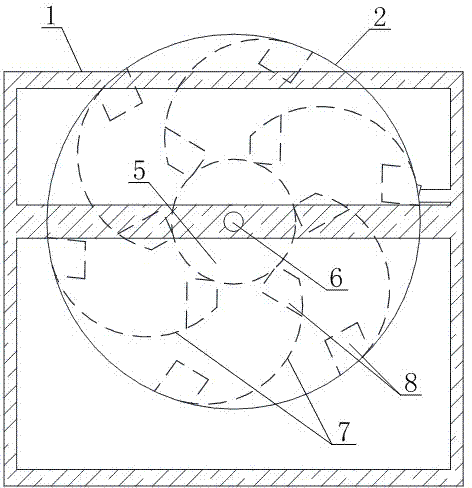
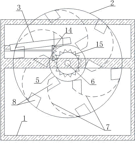
[0026] Such as Figure 1~4 As shown, a power output device includes a bracket 1, a turntable 2 arranged on the bracket and movably connected with it, and a ball channel 3 arranged on the bracket and fixedly connected with it and located on one side of the turntable. There are more than seven balls, and the two end openings of the ball channel are facing the turntable; the turntable includes two parallel and concentric circular plates 4, which are arranged between the two circular plates and are concentric with the circular plates The cylinder 5, and the rotating shaft 6 that runs through the two discs and the cylinder and is connected to the bracket, there are more than six sliding tracks 7 that are fixedly connected with the discs and can be rolled by the balls between the discs , all the sliding tracks are evenly distributed around the cylinder, and the sliding tracks are arc-shaped structures; two ends of each sliding track are respectively provided with an opening 8 that c...

Embodiment 2

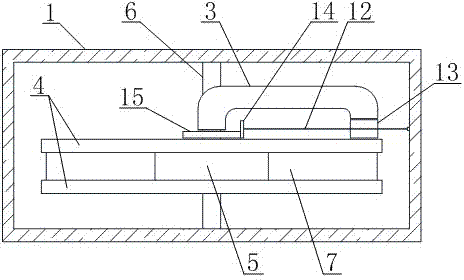
[0031] Such as Figure 5-7 As shown, the difference between this embodiment and Embodiment 1 is that the flipping member includes a linkage rod 12, four flip plates 13 evenly distributed on the outer wall of one end of the linkage rod and located at the bottom opening of the ball channel, and the linkage The universal joint 10 connected with the rod, the transmission rod 11 connected with the universal joint, and the second bevel gear arranged on the rotating shaft and meshed with the first bevel gear.

[0032] Implementation method of the present invention is as follows:

[0033] First, the user can do work on the turntable to make it rotate. During the rotation of the turntable, the second bevel gear rotates with the rotating shaft and drives the first bevel gear to rotate, and at the same time drives the turning plate to rotate to push the balls into the sliding track. When the sliding track reaches the top of the ball channel, it will automatically enter the ball channel ...


PUM


Abstract

The invention discloses a power output device to solve the problems that an existing power output machine is limited by the geology, the environment, the weather and other factors. The power output device comprises a support, a rotating plate and a roll ball channel, wherein the rotating plate is arranged on the support, the roll ball channel is arranged on the support, seven or more roll balls are arranged inside the roll ball channel, and the two end openings of the roll ball channel are right opposite to the rotating plate. The rotating plate comprises a cylinder, a rotating shaft and two circular plates, sliding tracks are arranged between the two circular plates, and each sliding track is provided with two openings. In addition, the roll ball channel is obliquely arranged, and the opening in the bottom end of the roll ball channel is provided with an overturning piece used for pushing the roll balls into the sliding tracks. The rotating plate can rotate relative to the support in the vertical plane through the roll balls, the roll balls can freely get in and out of the rotating plate, the gravitational potential energy of the roll balls is converted into kinetic energy, and therefore the rotating plate can output power in the rotating process.

Description

technical field [0001] The invention specifically relates to a power output device. Background technique [0002] At present, known power output machines include internal combustion engines and electric motors, etc., and they consume fuel oil and electric energy during work. With the deterioration of energy resources, chemical energy is becoming more and more scarce, and it pollutes the environment very much. Although there are clean energy sources such as wind energy and solar energy as power sports machines in addition, they cannot be popularized on a large scale due to factors such as environment and geography. Therefore, it is imminent to invent and create a power output device that is not limited by factors such as geography, environment, and weather. Contents of the invention [0003] The object of the present invention is to provide a power output device to solve the problem that the existing power output machine is limited by factors such as geography, environmen...

Claims


Application Information

Patent Timeline
Patent Type & Authority Applications(China)
IPC IPC(8): F03G3/08
Inventor 李三营
Owner 李三营
Why Eureka
Try Eureka