Bearing capable of detecting motion

A motion detection and bearing technology, which is applied in bearing components, shafts and bearings, bearing assembly, etc., can solve the problems of small reserved space between bearing body and supporting components, loss of magnetic sensor positioning, and increase of system cumulative error, etc., so as to facilitate automation Production, avoiding the accumulation of assembly errors, and improving the effect of assembly accuracy

Inactive Publication Date: 2014-06-25
宁波艾森博林轴承有限公司
View PDF6 Cites 8 Cited by
  • Summary
  • Abstract
  • Description
  • Claims
  • Application Information

AI Technical Summary

Problems solved by technology

[0004] This sensor bearing structure has the following defects: 1. The multi-pole magnetic ring is stepped, which is difficult to process. It is easy to deform the magnetic material ring during assembly, resulting in complete or partial damage to the magnetic material ring, which greatly reduces the detection accuracy; 2. 1. The Hall element in the magnetic sensor is first encapsulated in the plastic shell, and then radially limited in the installation groove, and the magnetic sensor is axially limited in the installation groove by the snap ring. This multiple positioning method increases The cumulative error of the system is reduced, and the positioning accuracy is low, which affects the detection accuracy; 3. The snap ring is directly riveted on the support element by rivets. The positioning of the magnetic sensor reduces the detection accuracy; 4. The reserved space between the bearing body and the supporting element is small, which makes it difficult to assemble; 5. The phase difference and duty cycle of the output rectangular wave are not ideal, which affects the detection accuracy

Method used


Image

  • Bearing capable of detecting motion
  • Bearing capable of detecting motion
  • Bearing capable of detecting motion

Examples


Embodiment Construction

[0028] The present invention will be described in detail below in conjunction with the accompanying drawings.

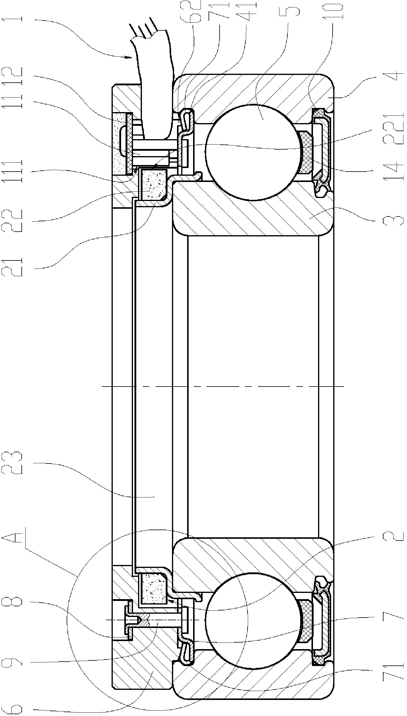
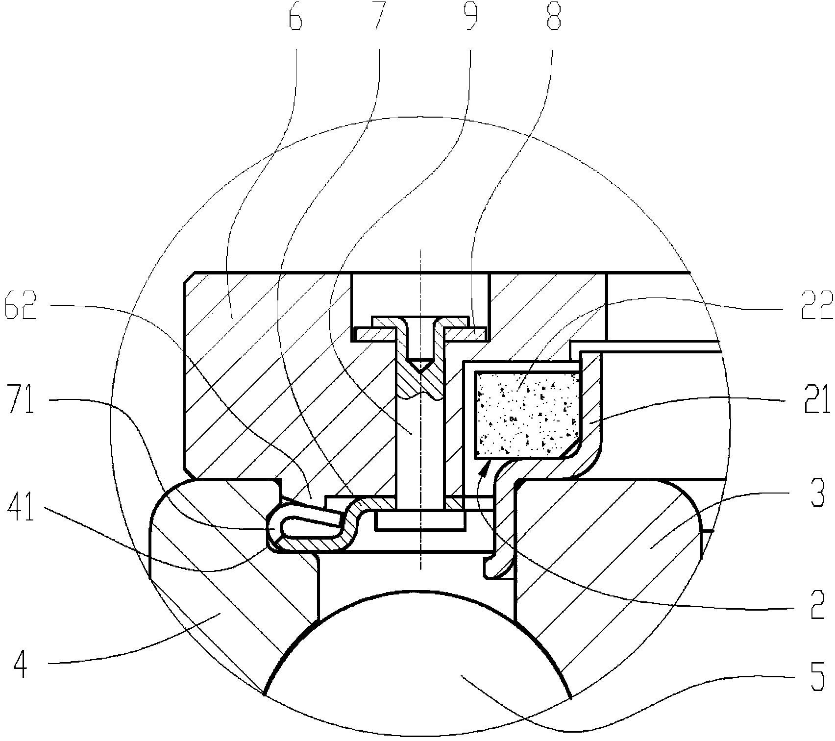
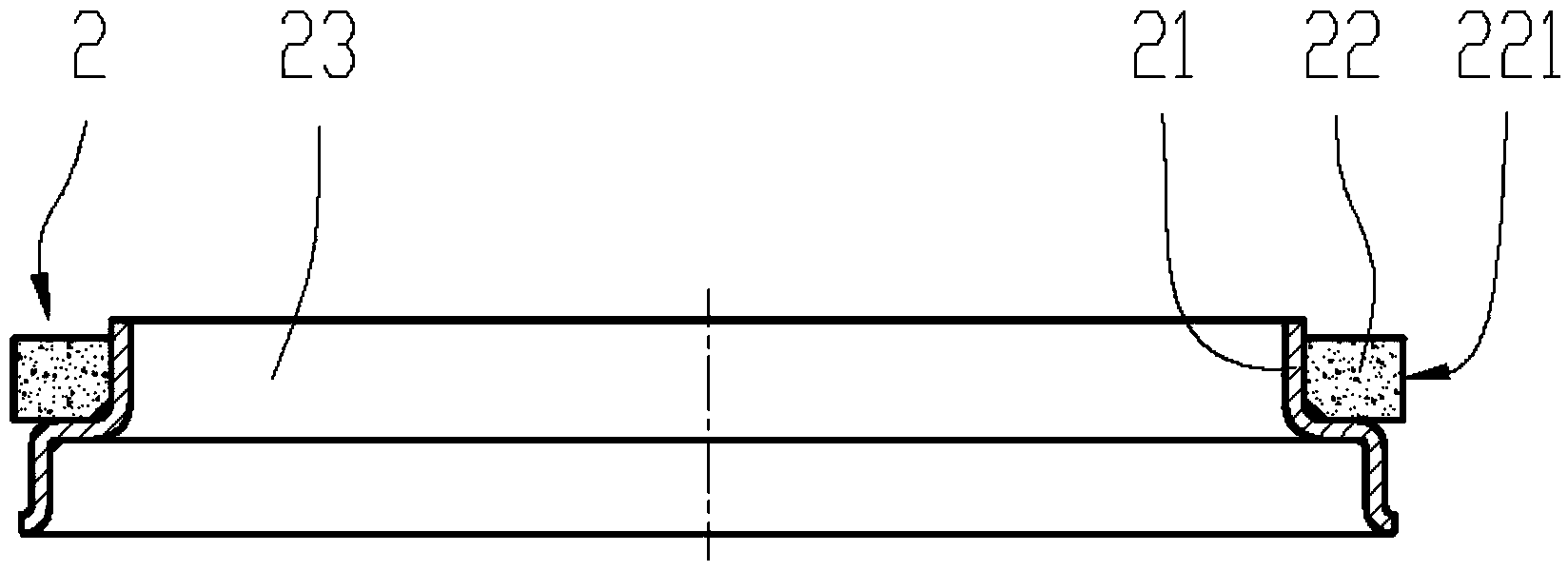
[0029] refer to Figure 1 to Figure 8 , the present invention provides a bearing with a motion detection function, including a bearing body, a magnetic sensor 1 and a multi-pole magnetic ring 2; the bearing body includes an inner ring 3, an outer ring 4, and a rolling element 5, and the setting of rolling Between the inner ring and the outer ring; the multi-pole magnetic ring 2 is fixedly installed on the upper end surface of the inner ring 3; and the magnetic sensor 1 is fixed on the outer ring 4 through the gland 6; The small stepped hole 61 at the lower end is radially provided with a through hole on the side wall of the gland 6. The through hole passes through the small hole at the lower end of the stepped hole 61 and extends to the inner wall of the gland 6. The magnetic sensor 1 is placed upside down in the stepped hole 61. On the stepped surface of the magnet...


PUM


Abstract

The invention discloses a bearing capable of detecting motion. The bearing comprise a bearing body, a magnetic sensor and a magnetic ring with multiple poles, wherein the bearing body comprises an inner ring, an outer ring and a rolling element; the magnetic ring is fixedly arranged at the upper end surface of the inner ring; the magnetic sensor is fixed on the outer ring through a pressing cover; a step hole of which the upper end is big and the lower end is small penetrates through the end surface of the pressing cover; a through hole is radially formed in the side wall of the pressing cover; the through hole penetrates through a small hole part of the lower end of the step hole and extends to the inner wall of the pressing cover; the magnetic sensor is arranged on the step surface of the step hole in an inverted manner and the sensing surface of the magnetic sensor is arranged opposite to the magnetized surface of the magnetic ring at an interval through the through hole; an insulating material is filled above the magnetic sensor, so that the magnetic sensor is firmly bonded in the step hole; the pressing cover is detachably arranged at the upper end surface of the outer ring. The bearing capable of detecting motion disclosed by the invention is small in assembly error, long in service life and capable of outputting two-channel rectangular wave which has a duty factor of 50% and a phase difference of 90 DEG, so that the detecting accuracy is improved.

Description

technical field [0001] The invention relates to a bearing, in particular to a bearing with a motion detection function. Background technique [0002] In order to detect the rotational speed and steering direction of the bearing, a multi-pole magnetic ring with a predetermined pattern and magnetization intensity is generally provided on either surface of the inner ring and the outer ring of the bearing, and a magnetic sensor installed on the other surface. The material has a plurality of patterns of magnetized portions arranged circumferentially. The multi-pole magnetic ring is composed of multiple magnetic pole pairs with N and S poles alternated in structure. The number of magnetic pole pairs is determined by the size of the bearing and the accuracy of detection. Generally, the larger the size, the higher the detection accuracy requirements, the corresponding The more pole pairs there are. The magnetic sensor is generally a Hall sensor, which has two Hall elements with st...

Claims


Application Information

Patent Timeline
Patent Type & Authority Applications(China)
IPC IPC(8): F16C41/00G01D5/244
Inventor 汪虹施国荣
Owner 宁波艾森博林轴承有限公司
Why Eureka
Try Eureka