Intelligent overhead line fault positioning and monitoring system

A technology of fault location and overhead lines, applied in the direction of fault location, etc., can solve problems such as wrong action information, fault indicator display information is not completely reliable, and reduce the time for fault finding, etc.

Inactive Publication Date: 2014-06-25
ZHUHAI GENE COSMOS ELECTRIC TECH
View PDF0 Cites 20 Cited by
  • Summary
  • Abstract
  • Description
  • Claims
  • Application Information

AI Technical Summary

Problems solved by technology

In the prior art, many companies have launched an intelligent fault monitoring system for this situation. The fault detection system consists of three modules: a fault indicator, a data acquisition communication terminal and a background server. When a line fails, the fault indication The device can display faults on the spot, and can upload the fault status information to the data collection communication terminal, and the data collection communication terminal then transmits the fault information to the master station, and the master station sends the action status of the fault indicator to relevant Emergency repair personnel, with the help of fault indicators, can quickly determine the branch and section of the fault location, greatly reducing the time for fault finding. However, only relying on the action information of the fault indicator to locate the fault, because the fault indicator Installed in the field, the environment is harsh, and the fault indicator is sometimes in the debugging state, and the action information error often occurs. The information displayed by the fault indicator is not completely reliable, resulting in inaccurate and low reliability of the fault location technology.

Method used


Image

  • Intelligent overhead line fault positioning and monitoring system
  • Intelligent overhead line fault positioning and monitoring system
  • Intelligent overhead line fault positioning and monitoring system

Examples


Embodiment Construction

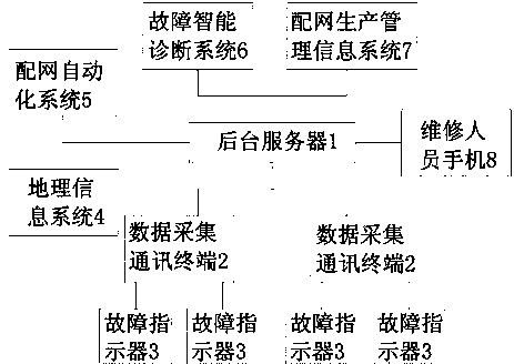
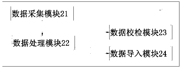
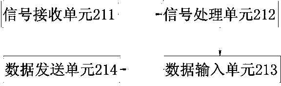
[0018] Such as figure 1 , figure 2 , image 3As shown, the present invention includes a background server 1, a data acquisition communication terminal 2 and a fault indicator 3 installed on the line, and the background server 1 is equipped with a fault location and monitoring platform and communicates with the data acquisition communication terminal through GPRS 2 to realize communication, the data acquisition communication terminal 2 communicates with multiple groups of the fault indicators 3 through radio frequency communication, and the intelligent overhead line fault location and monitoring system also includes Geographic information system 4, fault intelligent diagnosis system 6, distribution network automation system 5, and distribution network production management information system 7, the fault location and monitoring platform accesses the geographic information system after receiving the action message of the fault indicator 3 information system 4, and define all ...


PUM


Abstract

The invention discloses an intelligent overhead line fault positioning and monitoring system. The system is precise in fault positioning, high in precision and capable of quickly isolating faults, avoids long-time outage and improves operation reliability of a power grid. The intelligent overhead line fault positioning and monitoring system comprises a background server, a data collecting communication terminal, multiple fault indicators, a geographic information system and a distribution network automated system, wherein the background server, the data collecting communication terminal, the fault indicators, the geographic information system and the distribution network automated system are sequentially connected in a communication mode, and the geographic information system and the distribution network automated system are respectively connected with the background server. After a fault positioning and monitoring platform receives motion messages of the fault indicators, the geographic information system is accessed, all fault indicators which work and do not work on the same line are defined as upstream fault indicators and downstream fault indicators respectively, and a fault area is reduced to obtain a precisely positioned fault area by analyzing and determining the upstream fault indicators of a positioned fault area and the downstream fault indicators in the positioned fault area.

Description

technical field [0001] The invention relates to an intelligent overhead line fault location and monitoring system. Background technique [0002] With the development of society and economy, it is particularly important to build a self-healing, safe, economical and clean smart grid and provide high-quality power services. In the prior art, many companies have launched an intelligent fault monitoring system for this situation. The fault detection system consists of three modules: a fault indicator, a data acquisition communication terminal and a background server. When a line fails, the fault indication The device can display faults on the spot, and can upload the fault status information to the data collection communication terminal, and the data collection communication terminal then transmits the fault information to the master station, and the master station sends the action status of the fault indicator to relevant Emergency repair personnel, with the help of fault indic...

Claims


Application Information

Patent Timeline
Patent Type & Authority Applications(China)
IPC IPC(8): G01R31/08
Inventor 肖高林
Owner ZHUHAI GENE COSMOS ELECTRIC TECH
Why Eureka
Try Eureka