

Image forming apparatus featuring a multilayer member with a roughened layer surface to irregularly reflect incident light and method for making the multilayer member
- Summary
- Abstract
- Description
- Claims
- Application Information
AI Technical Summary
Benefits of technology
Problems solved by technology
Method used
Image

Examples
first embodiment
Color Stations
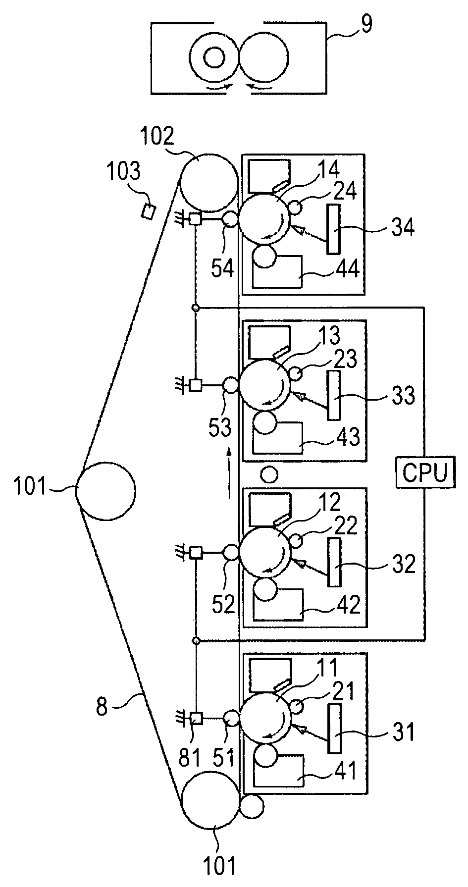
[0030] A description will be given of a tandem direct-transfer multicolor image forming apparatus (ETB system) according to a first embodiment of the present invention. FIG. 5 is a schematic sectional view of a color image forming apparatus (an image forming section in a laser printer or a copying machine) using an electrophotographic process.
[0031] In the image forming apparatus, four independent color stations corresponding to yellow (Y), magenta (M), cyan (C), and black (K) colors are vertically arranged in line, and each of the color stations includes an electrophotographic photoconductor, a developing device, and a cleaning device. In the image forming apparatus, a full-color image is obtained by transferring an image onto a recording material drawn on an electrostatic transportation belt in each color station while transporting the recording material.
[0032] Drum-shaped rotary electrophotographic photoconductors (hereinafter referred to as photoconductive drum...
second embodiment
[0082] An intermediate transfer method according to a second embodiment of the present invention will now be described. The second embodiment is advantageous in that the type of recording materials has less influence on the transfer than in the method using the ETB in the first embodiment.
Configuration of Image Forming Apparatus
[0083]FIG. 11 is a schematic structural view of an image forming apparatus according to the second embodiment. The image forming apparatus includes four image forming stations 1Y, 1M, 1C, and 1K that respectively form a yellow image, a magenta image, a cyan image, and a black image. The image forming stations 1Y, 1M, 1C, and 1K are arranged in line at regular intervals.
[0084] The image forming stations 1Y, 1M, 1C, and 1K respectively include photoconductive drums 2a, 2b, 2c, and 2d serving as image bearing members. Charging rollers 3a, 3b, 3c, and 3d, developing devices 4a, 4b, 4c, and 4d, primary transfer rollers 5a, 5b, 5c, and 5d, drum cleaning devices...
third embodiment
[0105] A basic configuration of a third embodiment of the present invention is similar to that of the above-described first embodiment.
[0106] In the third embodiment, a base layer is made of polyethylene terephthalate (PET) resin having a resistance adjusted to 1×10⁶ to 1×10¹¹ Ω.cm. A desired surface roughness Ra of the base layer is obtained by dispersing filler, such as glass fine particles, silica, PMMA, or boron nitride, as roughening particles in the base layer. A front coat layer is made of resin, such as acrylic resin, silicone hard coat resin, fluorocarbon resin, PC, or PMMA, on the surface of the base layer, in a manner similar to that employed in the first and second embodiments.
[0107] The surface roughness Ra of the base layer is set to be 0.11 to 0.15 μm by adjusting the mean diameter and mixing amount (mixing ratio) of the dispersed particles. A front coat layer having a thickness of 2.0 μm is provided on the base layer to form a two-layer belt. It was verified that t...
PUM
 Abstract
Description
Claims
Application Information