
Composite socket

A technology of sockets and double reeds, applied in the direction of electrical components, circuits, connections, etc., can solve problems such as short service life, large voltage drop, and easy deformation of reeds, and achieve the effect of avoiding unsafe factors and simplifying on-site operations

Active Publication Date: 2016-09-28
STATE GRID CORP OF CHINA +2
View PDF6 Cites 0 Cited by
  • Summary
  • Abstract
  • Description
  • Claims
  • Application Information

AI Technical Summary

Problems solved by technology

[0004] However, it has the following disadvantages. The contact surface between the reeds of the composite socket in the intelligent junction box is small, and the contact surface between the reeds is similar to a line contact. After repeated plugging and unplugging, the impedance of the contact surface will increase. Increase the pressure drop, causing the reed to heat up; the reed is prone to deformation after a long time, and the service life is short; the reed and the copper column are mainly connected by welding, and the pressure drop is large

Method used


Image

  • Composite socket
  • Composite socket
  • Composite socket

Examples


Embodiment Construction

[0032] In order to enable those skilled in the art to better understand the present invention, the technical solution of the present invention will be further described below in conjunction with the accompanying drawings and embodiments.

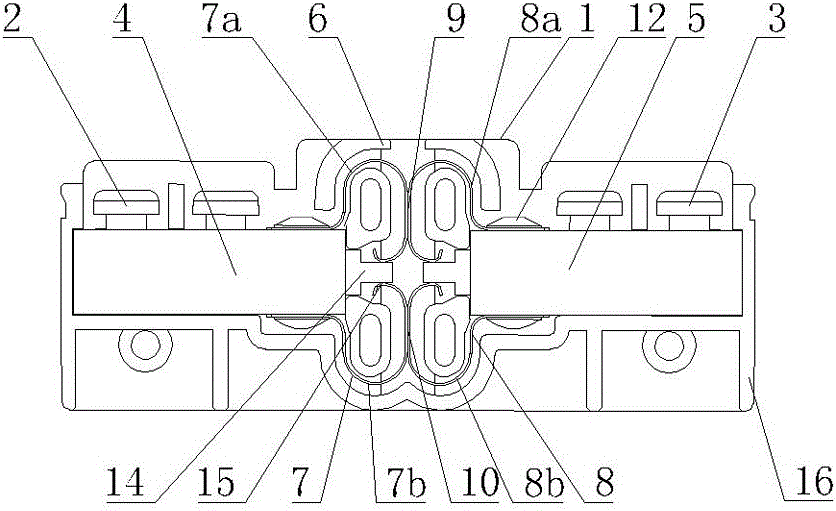
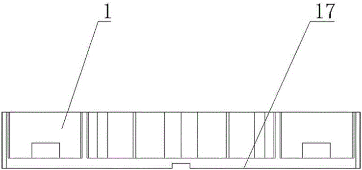
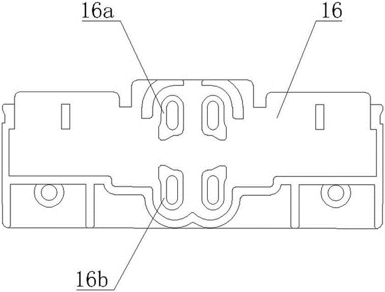
[0033] Such as figure 1 , figure 2 , image 3 , Figure 4 As shown, the composite socket includes a shunt socket 1, and the shunt socket 1 includes a front terminal 2, a rear terminal 3, a front copper column 4, a rear copper column 5, a socket 6 and a bottom plate 16, and the socket 6 includes a front double reed 7 And the rear double reed 8, the front double reed 7 is connected with one end of the front terminal 2 through the front copper column 4, and the other end of the front terminal 2 is connected with the billing gate watt-hour meter, which can read voltage, current, pulse and Communication and other signals, the rear double reed 8 is connected to one end of the rear terminal 3 through the rear copper column 5, and the other end ...


PUM


Abstract

The invention discloses a novel multi-cable socket, and relates to a connecting device of an electric system. The novel multi-cable socket is used for solving the problems that after multiple times of inserting and pulling are carried out, the impedance of contact faces between reeds can be increased to a certain degree, the voltage drop is increased, and accordingly the reeds are heated; the reeds are prone to generating deformation after a long time, and the service life is short are solved. The novel multi-cable socket comprises shunt socket bodies. Each shunt socket body comprises the front wiring end, the rear wiring end, a front copper column, a rear copper column, an insertion opening and a base plate, the insertion opening comprises a front double-reed sheet and a rear double-reed sheet, the front double-reed sheet comprises an upper single-reed sheet and a lower single-reed sheet which are separated, the rear double-reed sheet comprises an upper single-reed sheet and a lower single-reed sheet which are separated, the opposite faces of the front ends of the upper single-reed sheets of the front double-reed sheet and the rear double-reed sheet are bent to form upper contact faces, the upper single-reed sheets of the front double-reed sheet and the rear double-reed sheet are connected through the upper contact faces, the opposite faces of the front ends of the lower single-reed sheets of the front double-reed sheet and the rear double-reed sheet are bent to form lower contact faces, and the lower single-reed sheets of the front double-reed sheet and the rear double-reed sheet are connected through the lower contact faces; limiting protrusions are arranged at the opposite ends of the front copper column and the rear copper column respectively; due to the fact that the shunt socket bodies are improved, the multi-cable socket is reliable.

Description

technical field [0001] The invention relates to a wiring device for a power system, more specifically, a composite socket for an electrical secondary circuit. . Background technique [0002] In the power system, the electric energy meter (electric energy meter) connected to the secondary circuit is connected to the secondary metering circuit of the substation by a joint terminal junction box to transmit voltage and current signals. The connection method is screw and metal slide connection, as The circuit meters of legal metering instruments must be regularly checked annually. The current method is to use a composite intelligent terminal junction box. [0003] Patent document 201220711690.8 (application date: 2012.12.21) discloses a composite intelligent terminal junction box, including a front terminal, a rear terminal and a composite socket. The terminal is connected to the lower reed of the composite socket through a wire. The composite socket is composed of 10 shunt soc...

Claims


Application Information

Patent Timeline
IPC IPC(8): H01R9/00H01R9/24
Inventor 何国军侯兴哲周孔均林伟唐晓泽程瑛颖杨华潇魏麟肖冀
Owner STATE GRID CORP OF CHINA
Learn More