

Automatic power supply unit for refrigerated containers
A technology for refrigerated containers and automatic power supply, which is applied to circuit devices, electrical components, and transportation passenger cars, etc., can solve problems such as low efficiency, potential safety hazards, and damage, and achieve the effects of convenient use, improved power supply efficiency, and enhanced reliability.
- Summary
- Abstract
- Description
- Claims
- Application Information
AI Technical Summary
Problems solved by technology
Method used
Image

Examples
Embodiment 1
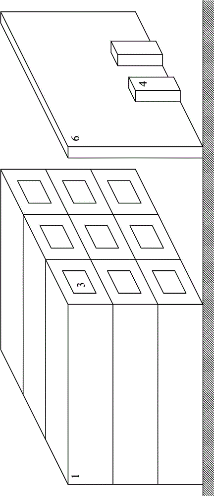
[0028] An automatic power supply device for refrigerated containers, the packaging box 1, the electrical load 2, the current collector 3, the power cabinet 4, the transmitting module 5 and the induction wall 6, such as Figure 1 ~ Figure 3 As shown, the specific structure is:
[0029] An electric load 2 is provided in the cabinet 1. In this embodiment, a refrigerator is used for the electric load 2. Note that the cold air outlet of the refrigerator should face the inside of the cabinet 1;
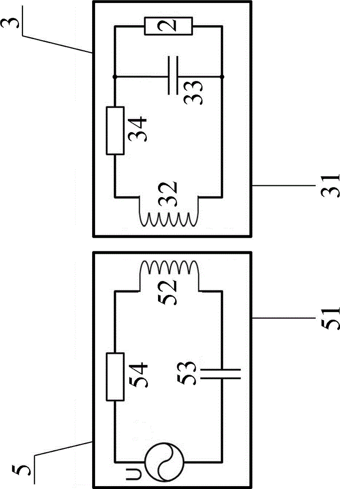
[0030] Each box 1 is fixed with a current collector 3, such as figure 2 As shown, it includes a current collecting shell 31, a current collecting coil 32, a current collecting capacitor 33, and a current collecting resistor 34. The inner end surface of the current collecting shell 31 is fixed on one end surface of the box body 1. The capacitor 33 and the current collecting resistor 34 are both arranged in the current collecting shell 31, the current collecting coil 32 is attached to the inner s...
Embodiment 2
[0037] An automatic power supply device for refrigerated containers. The packaging box body 1, the electric load 2, the current collector 3, the power cabinet 4, the transmitting module 5 and the induction wall 6, and also includes a cushion 7, such as Figure 4 with Figure 5 As shown, the buffer pad 7 is fixed on the outer end surface of the current collector housing 31, and the thickness of the buffer pad 7 is not greater than 40 mm. The other structures are the same as in Example 1.
[0038] When this embodiment is used, the box 1 of the refrigerated container is stacked on the dock site as required, so that the collector shell 31 gradually approaches the launch shell 51. When the buffer pad is against the launch module 5, it indicates that the launch coil 52 and The distance between the collector coils 32 meets the requirements. Other methods of use are the same as in Example 1.
Embodiment 3
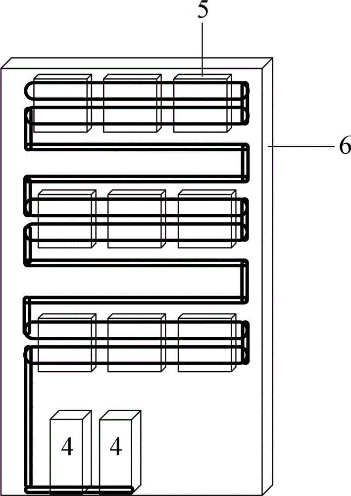
[0040] An automatic power supply device for refrigerated containers. The packaging box body 1, the electric load 2, the current collector 3, the power cabinet 4, the transmitting module 5 and the induction wall 6, and also includes a cushion 7, such as Image 6 As shown, the buffer pad 7 is fixed on the outer end surface of the emitting shell 51, and the thickness of the buffer pad 7 is not greater than 40 mm.
[0041] Other structures and methods of use are the same as in Example 2.
PUM
 Abstract
Description
Claims
Application Information