
A Constant On-time Controller for Switching Power Supply with External Compensation

A fixed on-time, switching power supply technology, used in control/regulation systems, instruments, electrical components, etc., can solve the problem of difficult to meet the high-precision technical indicators of output voltage, DC bias, and high power supply accuracy requirements, and achieve a simple structure. , the effect of eliminating the DC offset, and the number of components is small

Inactive Publication Date: 2016-08-31
SHANGHAI UNIVERSITY OF ELECTRIC POWER
View PDF3 Cites 0 Cited by
  • Summary
  • Abstract
  • Description
  • Claims
  • Application Information

AI Technical Summary

Problems solved by technology

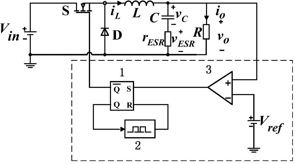
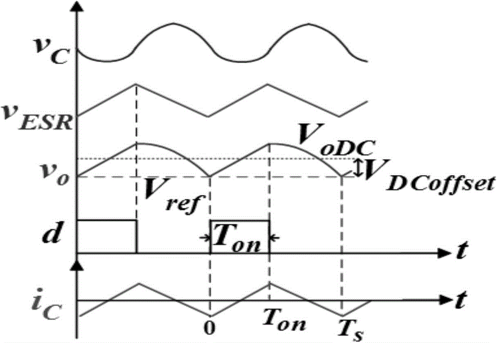
However, this control method has a disadvantage that there is a DC bias problem. Because some electronic devices, such as computers, have high requirements on the accuracy of the power supply, and due to the characteristics of fixed on-time control, the output voltage must be greater than the reference voltage. This necessarily results in a DC offset between the average value of the output voltage and the reference voltage
Therefore, the traditional fixed on-time control method is difficult to meet the high-precision technical specifications of the output voltage

Method used


Image

  • A Constant On-time Controller for Switching Power Supply with External Compensation
  • A Constant On-time Controller for Switching Power Supply with External Compensation
  • A Constant On-time Controller for Switching Power Supply with External Compensation

Examples


Embodiment Construction

[0022] The present invention will be described in detail below in conjunction with the accompanying drawings and specific embodiments. This embodiment is carried out on the premise of the technical solution of the present invention, and detailed implementation and specific operation process are given, but the protection scope of the present invention is not limited to the following embodiments.

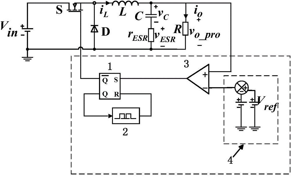
[0023] Such as figure 2 As shown, a switching power supply fixed on-time controller with external compensation, the switching power supply includes a MOSFET switch tube S, a power diode D, a filter inductor L, a filter capacitor C, and an equivalent series resistance r of the filter capacitor ESR and load R, the filter inductor current is i L , the filter capacitor voltage is v c , the voltage across the equivalent series resistance is V ESR , the load current is i o ; The fixed on-time controller includes an RS flip-flop 1, a time delayer 2 and a comparator 3, the time delayer 2...


PUM


Abstract

The invention relates to a switching power source fixed on-time controller with external compensation. A switching power source comprises an MOSFET switching tube. The fixed on-time controller comprises an RS trigger, a time delayer and a comparator. The time delayer is connected with the RS trigger, the output end of the RS trigger is connected with the MOSFET switching tube, the input end of the RS trigger is connected with the output end of the comparator, one input end of the comparator is connected with the output end of the switching power source, and the other input end of the comparator is connected with a direct current bias correcting circuit. The direct current bias correcting circuit comprises a subtracter, a digital processor and a reference voltage. One end of the subtracter is connected with the comparator, and the other end of the subtracter is connected with the digital processor and the reference voltage. The digital processor and the reference voltage are respectively grounded, and the digital processor outputs the voltage compensation amount to the subtracter. Compared with the prior art, the witching power source fixed on-time controller has the advantages of effectively eliminating direct current bias and being simple in structure.

Description

technical field [0001] The invention relates to a switching power supply, in particular to a constant conduction time controller of a switching power supply with external compensation. Background technique [0002] With the rapid development of mobile devices, DC-DC choppers as their power management systems, that is, switching power supplies, must meet the following technical requirements: (1) low output voltage; (2) high output voltage accuracy; (3) small size; (4) When the output load is transient, the transient overshoot of the output voltage is small. The above requirements put forward higher requirements on the steady-state and dynamic characteristics of the switching power supply, and pose new challenges to the control method of the switching power supply. Among them, the traditional fixed on-time control method is widely used in switching power supplies because it meets the basic requirements of stability, dynamic performance and simplicity. Traditional fixed on-tim...

Claims


Application Information

Patent Timeline
Patent Type & Authority Patents(China)
IPC IPC(8): H02M3/155H02M1/08
Inventor 赵晋斌刘争光屈克庆
Owner SHANGHAI UNIVERSITY OF ELECTRIC POWER
Learn More