
Device for controlling a flow of coolant and/or lubricating oil

A technology of lubricating oil flow and lubricating oil, applied in the direction of valve operation/release device, valve device, fluid-driven clutch, etc., can solve the problems of increased traction torque, transmission efficiency burden, etc., to avoid friction loss and avoid friction loss and leakage loss, avoiding the effect of plug connection

Inactive Publication Date: 2014-06-25
ZF FRIEDRICHSHAFEN AG
View PDF6 Cites 9 Cited by
  • Summary
  • Abstract
  • Description
  • Claims
  • Application Information

AI Technical Summary

Problems solved by technology

A problem with the oil cooling of the friction linings is that (especially when the clutch is disengaged) the cooling oil between the friction linings leads to an increase in the traction torque, which has a negative impact on the circulation of the lubricating oil pump and thus also on the efficiency of the transmission burden

Method used


Image

  • Device for controlling a flow of coolant and/or lubricating oil
  • Device for controlling a flow of coolant and/or lubricating oil
  • Device for controlling a flow of coolant and/or lubricating oil

Examples


Embodiment Construction

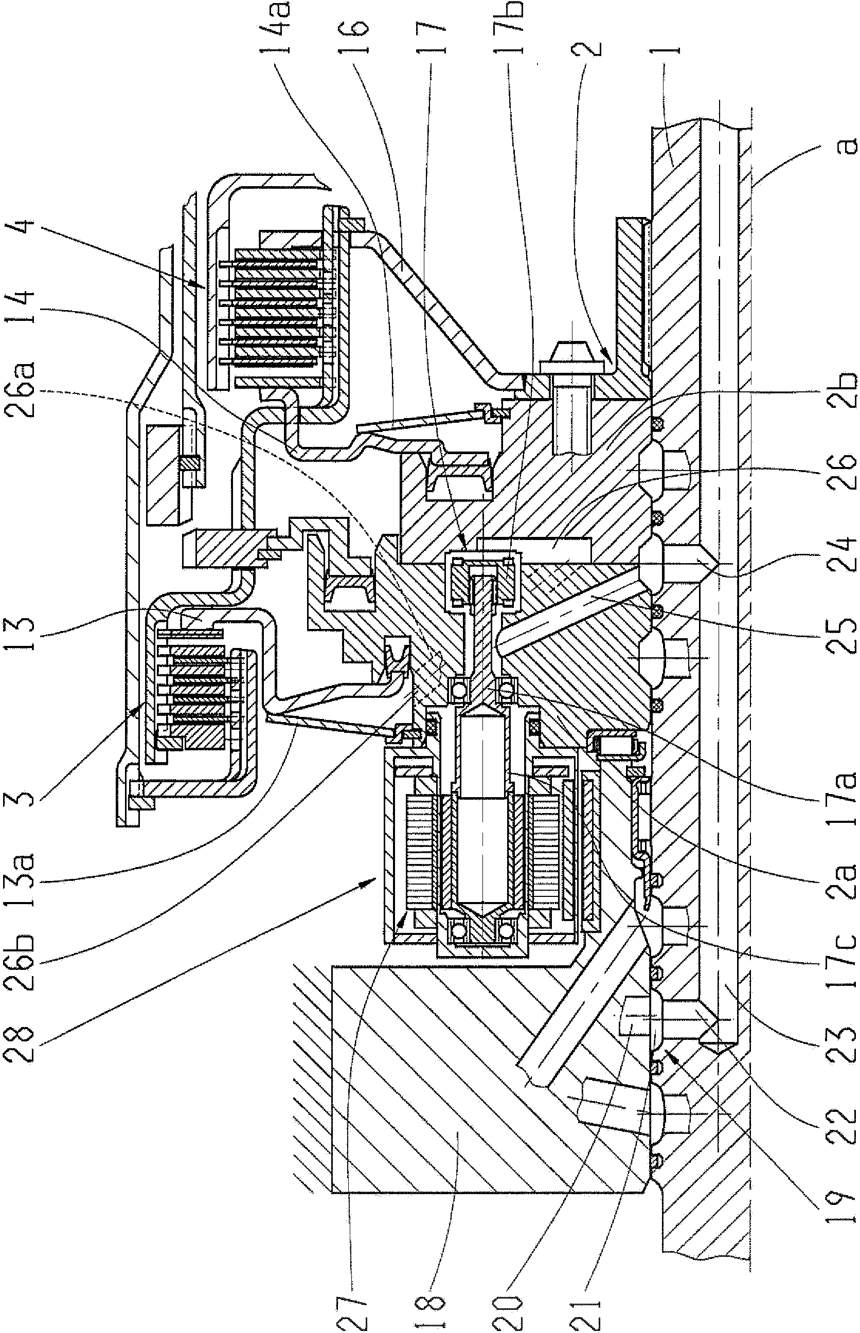
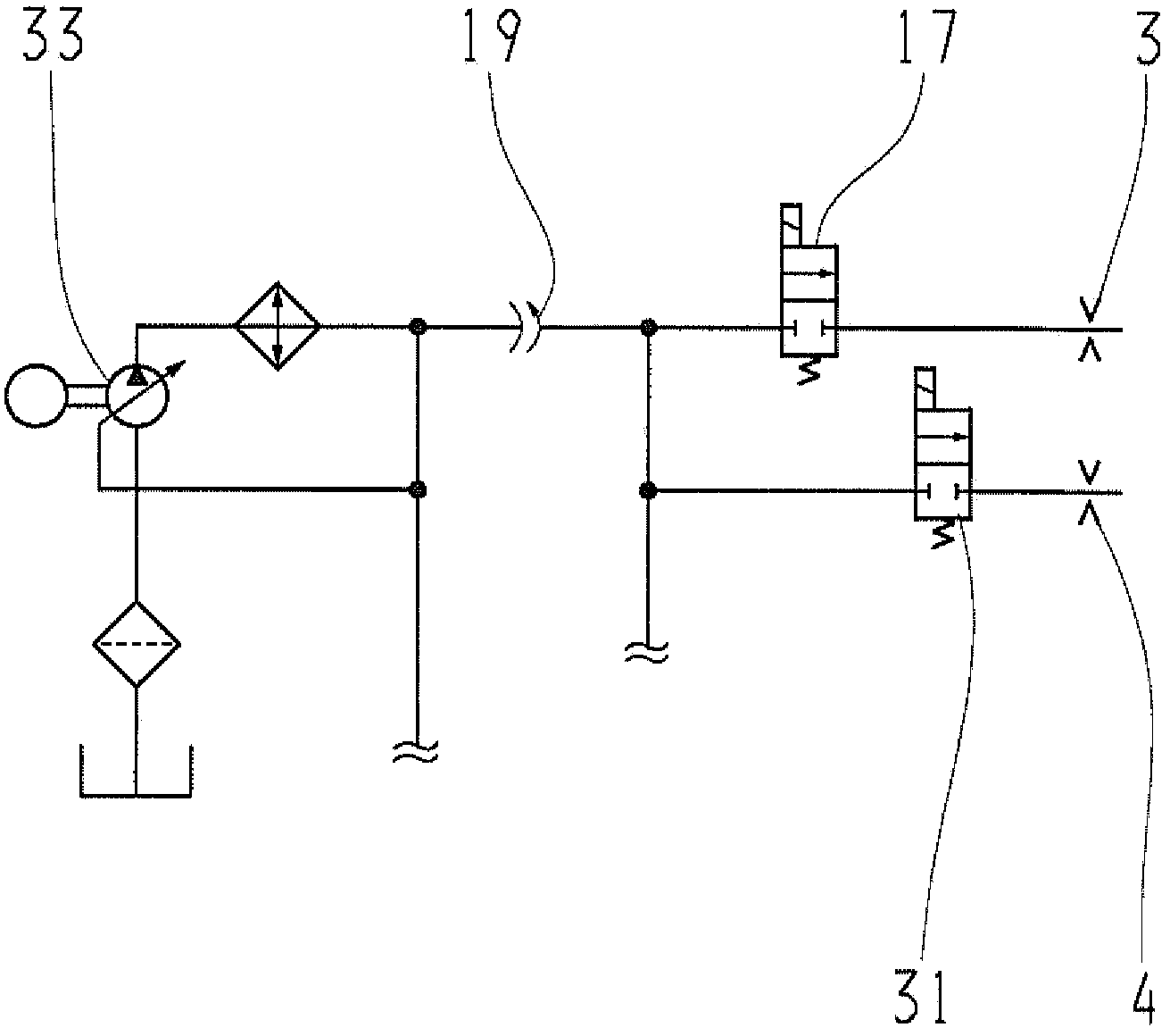
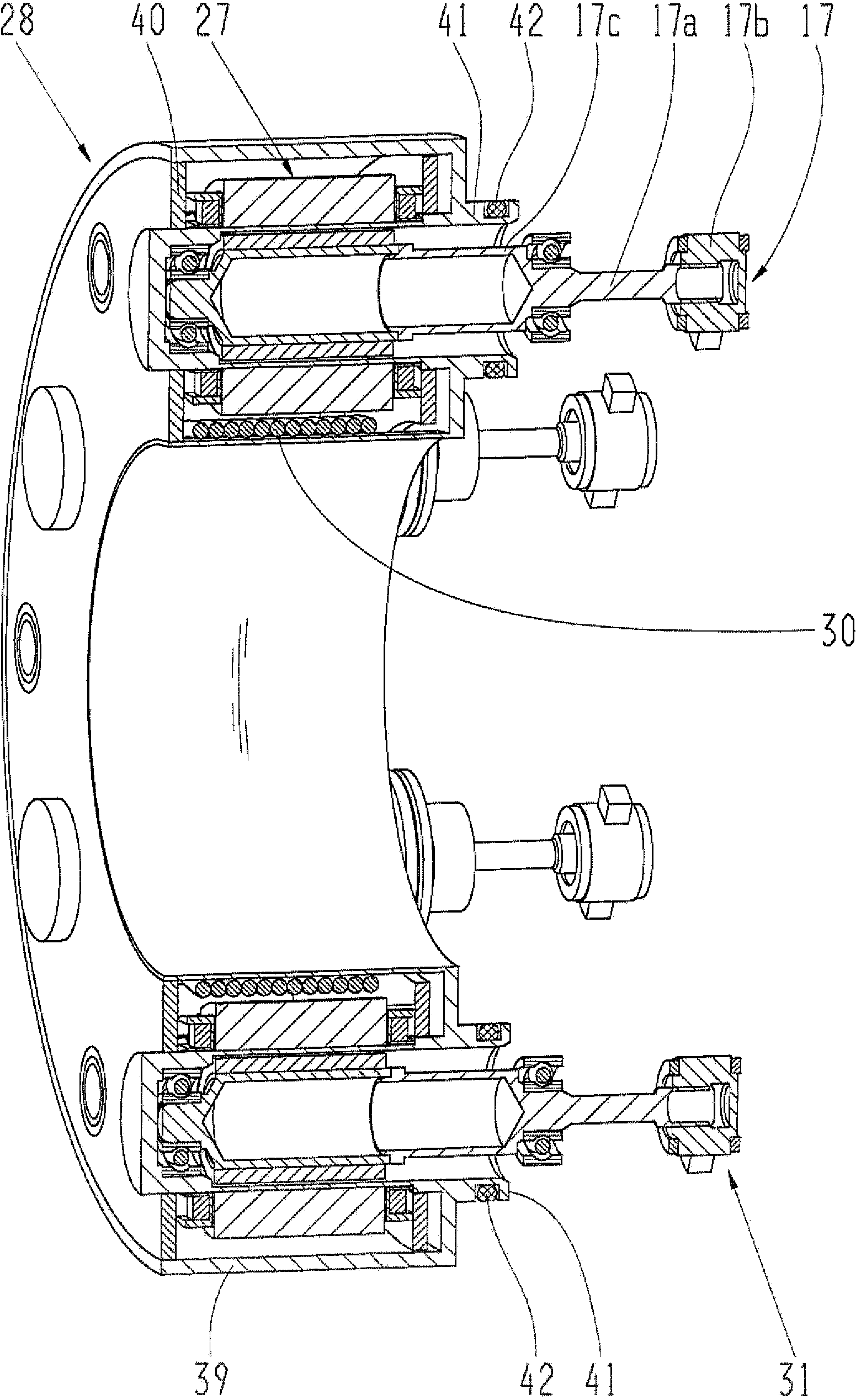
[0028] figure 1 A device for the control of cooling oil flow of an automatic transmission of a motor vehicle is shown. A so-called function carrier 2 with an axis of rotation a is arranged on the drive shaft 1 in a rotationally fixed manner. A first cooling point, which is designed as a multi-plate clutch 3 , and a second cooling point, which is designed as a multi-plate clutch 4 , are connected by means of the functional carrier 2 . The first multiplate clutch 3 is actuated by a first annular piston 13 and the second multiplate clutch 4 is actuated by a second annular piston 14 . Disk springs 13 a , 14 a supported on the functional carrier 2 are provided for restoring the annular pistons 13 , 14 . The drive sides of the shifting elements 3 , 4 are connected to the drive shaft 1 via the connecting element 16 and the functional carrier 2 . The functional carrier 2 is therefore also the carrier of the shifting elements 3 , 4 .

[0029]According to the invention, a valve 17 ,...


PUM


Abstract

The invention relates to a device for controlling at least one flow of coolant and / or lubricating oil by at least one valve (17) for at least one cooling and / or lubricating point (3, 4) connected to a shaft (1). According to the invention, the valve (17) can be electrically actuated and is connected to the at least one cooling and / or lubricating point (3, 4) in a rotationally fixed manner, and the electrical energy for actuating the valve (17) can be supplied in a contactless manner.

Description

technical field [0001] The invention relates to a device for controlling the flow of cooling oil and / or lubricating oil according to the preamble of claim 1 and to the use of the device. Background technique [0002] Multi-plate shifting elements are used in motor vehicle transmissions, especially in automatic transmissions, as clutches and brakes for shifting gears. The actuation, ie closing and opening, of the shift elements is generally performed hydraulically, wherein a transmission oil pump is provided for its own hydraulic circuit. When the multi-plate shifting element is closed, heat is generated during the pressing of the friction disks against one another, so the shifting element must be cooled in order to avoid overheating and possible damage to the friction disks or the friction linings. For this purpose, it is known to supply cooling oil from the lubricating oil circuit to the disk packs of the shifting elements via suitable distribution mechanisms. A problem w...

Claims


Application Information

Patent Timeline
Patent Type & Authority Applications(China)
IPC IPC(8): F16D25/12
CPCF16D25/12F16D25/123F16D25/10F16D25/0638F16K31/02F16D13/72
Inventor 马蒂亚斯·赖施拉尔夫·德雷霍尔茨
Owner ZF FRIEDRICHSHAFEN AG
Learn More