CVT (constant-voltage transformer) driving system and motorcycle

A drive system and driven shaft technology, applied in vehicle components, control devices, transportation and packaging, etc., can solve problems such as affecting the shockproof, compact and safety performance of the whole vehicle, affecting the long-term operation of the transmission mechanism, and adversely affecting the heat dissipation of the transmission mechanism. , to achieve the effect of facilitating heat dissipation, convenient installation and arrangement, and smooth heat dissipation

Inactive Publication Date: 2014-07-02
CHONGQING LONCIN ENGINE
View PDF6 Cites 5 Cited by
  • Summary
  • Abstract
  • Description
  • Claims
  • Application Information

AI Technical Summary

Problems solved by technology

For motorcycles, the arrangement space for the engine and CVT is limited, especially for the structure where the drive is directly output to the wheels (directly through the differential), due to the limited space and the need for stable and firm suspension, the horizontal arrangement The transmission structure makes the installation of the engine and CVT uncoordinated, which affects the shockproof, compactness and safety performance of the whole vehicle; at the same time, the layout structure between the main and driven shafts of the existing CVT adopts a horizontal parallel method for placing two The housing cavity between the two is also horizontal; due to the transmission of the CVT structure, more heat will be generated. normal long-term operation of

Method used


Image

  • CVT (constant-voltage transformer) driving system and motorcycle
  • CVT (constant-voltage transformer) driving system and motorcycle
  • CVT (constant-voltage transformer) driving system and motorcycle

Examples


Embodiment Construction

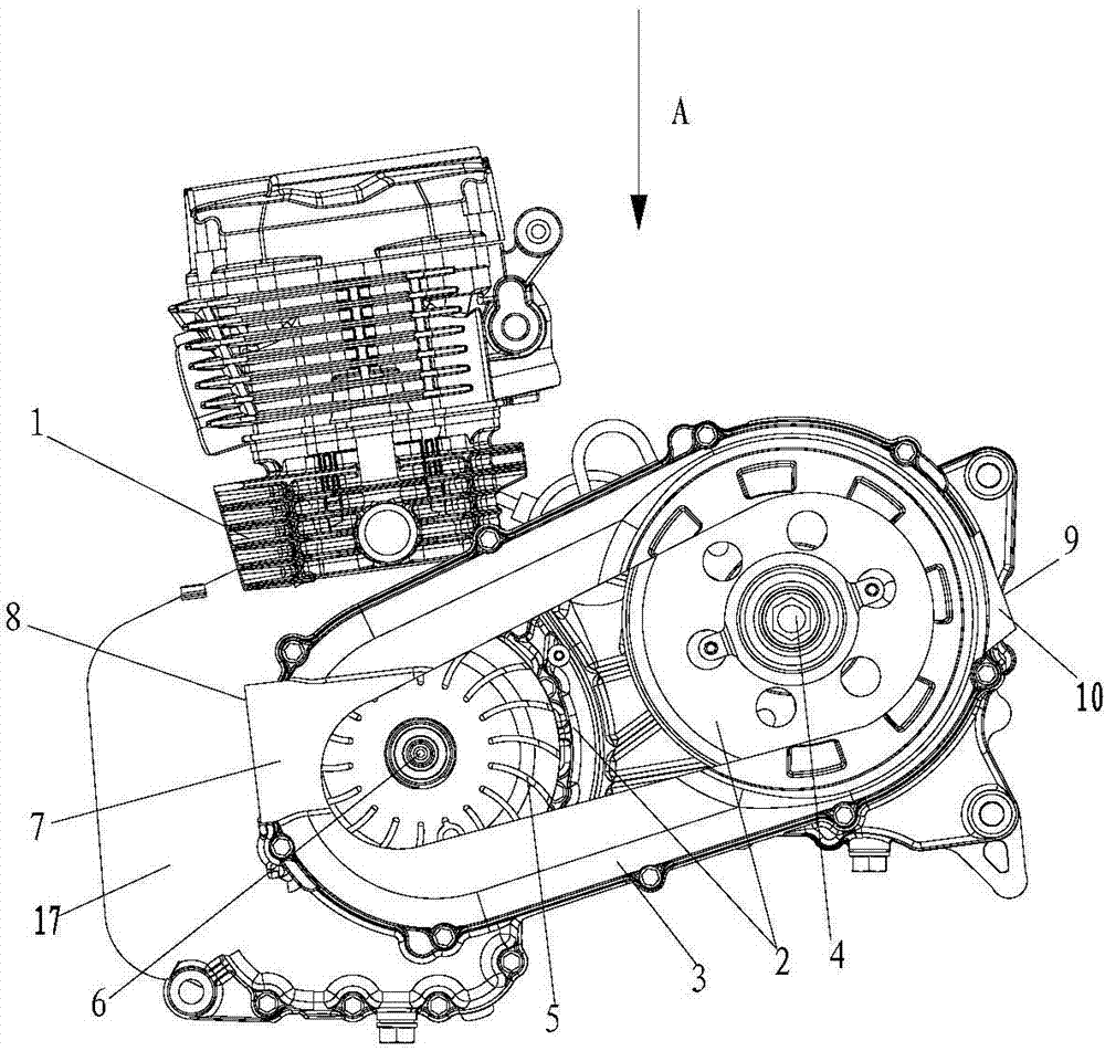
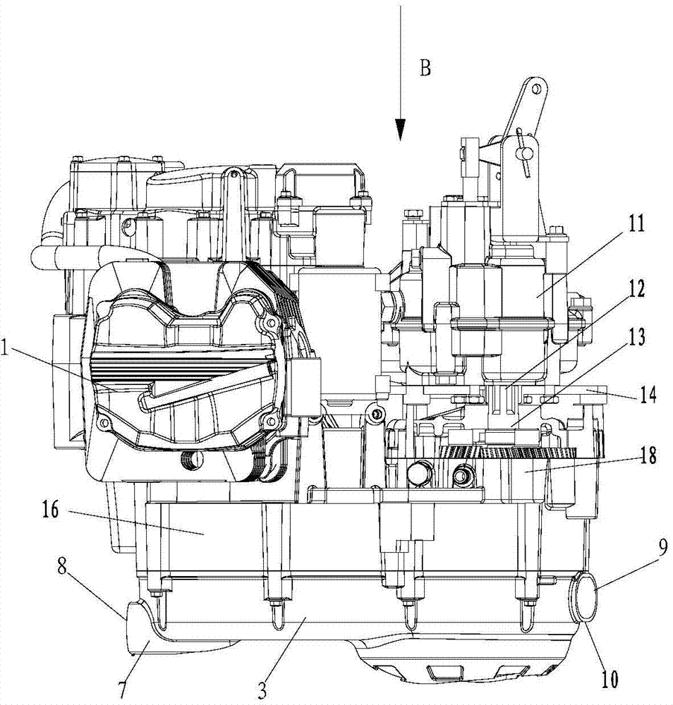
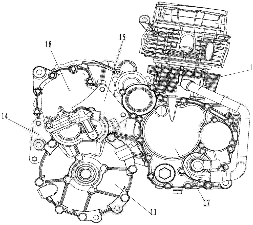
[0021] figure 1 It is a structural schematic diagram of the present invention, figure 2 for figure 1 View along direction A, image 3 for figure 2 View along direction B, Figure 4 It is a schematic diagram of the three-dimensional structure of the present invention (remove the side end cover), as shown in the figure: the CVT drive system of this embodiment includes an engine 1 and a CVT2 that cooperates with the crankshaft transmission of the engine, the driving shaft 6 of the CVT and the driven shaft of the CVT 4 parallel, and the driven shaft 4 of the CVT is located obliquely above the driving shaft 6 of the CVT; the driving shaft 6 of the CVT can be the engine power output shaft, and the structure of the CVT will not be repeated here. As shown in the figure, the engine 1 Power is output through the crankshaft in the crankcase 17, and the power output shaft section extends out of the crankcase 17 to form the CVT drive shaft 6. The CVT drive shaft 6 is equipped with a ...


PUM


Abstract

The invention discloses a CVT (constant-voltage transformer) driving system and a motorcycle. The CVT driving system comprises an engine and a CVT, wherein a driving shaft of the CVT and a driven shaft of the CVT are parallel to each another and are in transmission fit with each other; and the driven shaft of the CVT is positioned above the driving shaft of the CVT. Because the driven shaft of the CVT is placed above the driving shaft of the CVT, the mounting distance is shortened. The CVT driving system has a compact mounting structure, and is applicable to a motorcycle (particularly a three-wheeled motorcycle); the overall arrangement of the whole motorcycle is coordinated; safety requirements on shock absorption of the motorcycle can be well met; the CVT and the engine can be mounted on a driving portion together and are used for directly driving wheels; because the whole size of the CVT driving system is reduced, mounting space is reduced, the CVT driving system is mounted and arranged conveniently, and the manufacturing cost of whole driving equipment is saved; and because the CVT driving system has an inclined structure, an air convection principle can be implemented in the CVT shell, namely, hot air ascends and cold air descends in the CVT shell, the CVT shell is suitable for convection flowing of heat, heat dissipation of the heat dissipation channel is smooth, and heat dissipation on the CVT transmission mechanism is facilitated.

Description

technical field [0001] The invention relates to a motorcycle transmission system and the motorcycle, in particular to a CVT drive system and the motorcycle. Background technique [0002] CVT (continuously variable transmission) used in motor vehicles has good economy, power and driving comfort, and reduces emissions and costs. Therefore, there are also technical solutions for using it in motorcycles in the prior art, thereby improving the quality of motorcycles. economic performance of the car. In the prior art, the CVT is used in the installation of motorcycles (including three-wheeled motorcycles). In order to ensure the standardization and versatility of the installation, the CVT and the engine are installed horizontally, that is, the drive shaft of the CVT (the power output of the engine) Segment axis) line and the axis of the driven shaft of CVT are in the same horizontal plane, which is convenient for installation and transmission. For motorcycles, the arrangement sp...

Claims


Application Information

Patent Timeline
Patent Type & Authority Applications(China)
IPC IPC(8): B60K17/06
Inventor 翟明明徐良李学龙汪朝杨生华
Owner CHONGQING LONCIN ENGINE
Why Eureka
Try Eureka