Capacitor platform for series compensator

A capacitor and capacitor bank technology, which is applied in circuit devices, substations/switchgear boards/panels/desks, electrical components, etc., can solve the problem that the platform layout of 1000kV/750kV capacitors cannot achieve the expected effect, and the installation technology and installation process requirements are relatively high. High, the capacity of the damping device is increased, etc., to achieve the effect of reasonable structure, balanced force, and compact layout of the layout plan

Active Publication Date: 2014-05-21
CHINA EPRI SCIENCE & TECHNOLOGY CO LTD +2
View PDF2 Cites 0 Cited by
  • Summary
  • Abstract
  • Description
  • Claims
  • Application Information

AI Technical Summary

Problems solved by technology

With the increase of the voltage level (750kV, 1000kV) the capacitor units increase significantly, and the structure of a single H-bridge connection can no longer meet the application needs. It is necessary to adopt a double-H-bridge parallel structure, or even a three-H-bridge parallel structure; the capacity of the damping device also increases accordingly. Large, need to use parallel scheme
Considering that there are many devices on the capacitor platform of the series compensator device, the connection is relatively complicated, and at the same time, it needs to meet the corresponding electrical insulation performance on the basis of satisfying maintenance and convenient replacement of devices. Therefore, the metal oxide voltage limiter MOV, spark The installation technology and installation process requirements for gaps and damping devices are relatively high
[0006] These are quite different from the existing 500kV series compensation. Copying the layout of the existing 500kV capacitor platform can no longer achieve the expected effect of the layout of the 1000kV / 750kV capacitor platform.

Method used


Image

  • Capacitor platform for series compensator
  • Capacitor platform for series compensator
  • Capacitor platform for series compensator

Examples


specific Embodiment approach

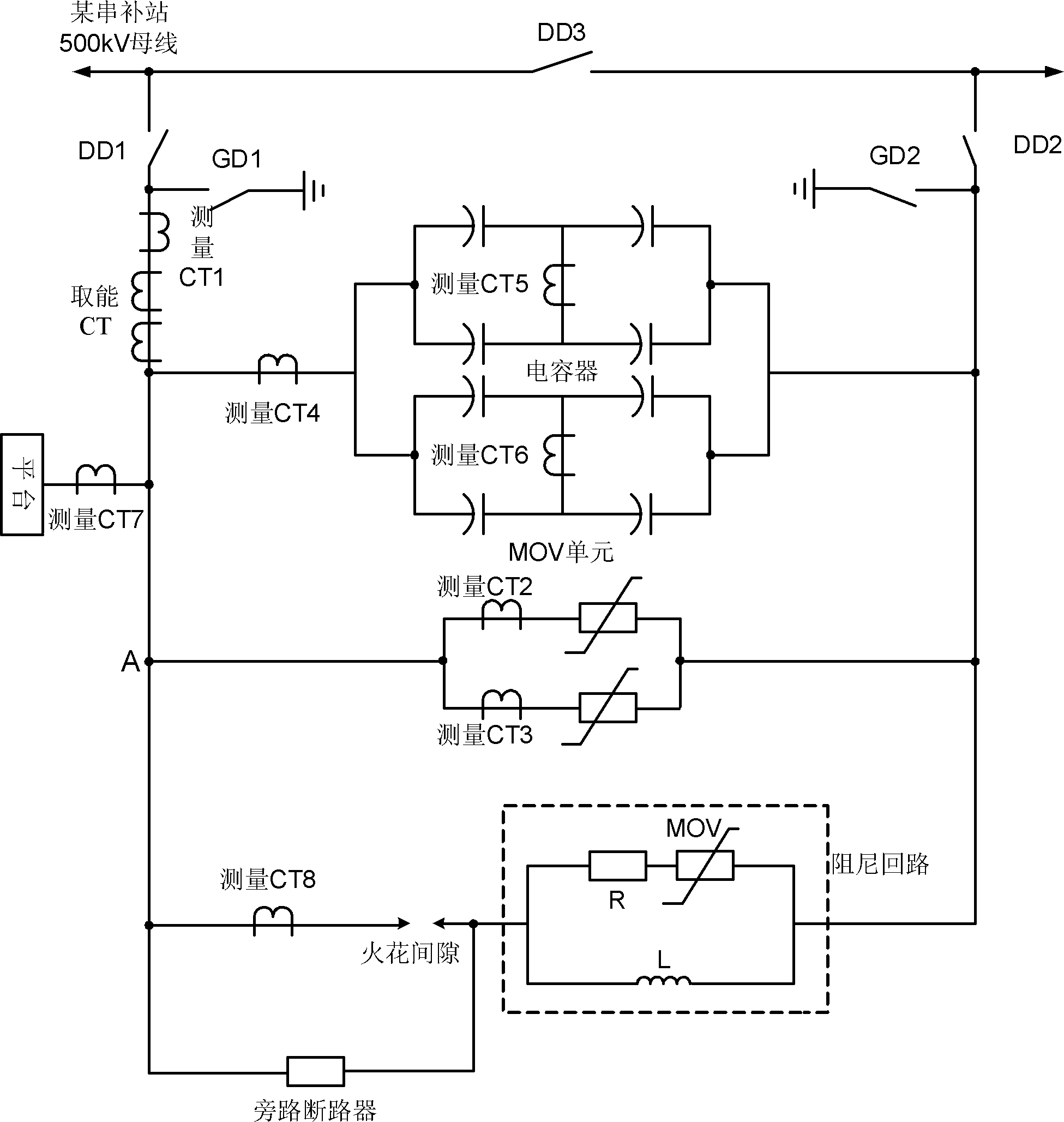
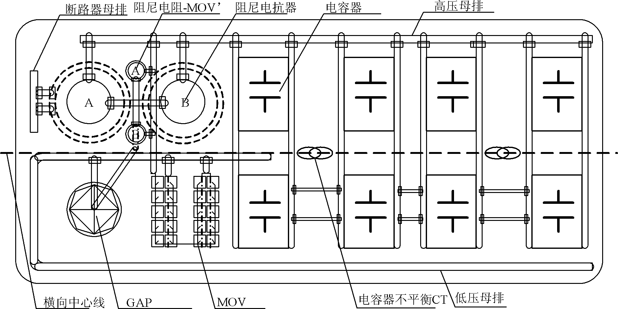
[0036] figure 1 The fixed series compensation single-phase schematic diagram using double H-bridge wiring for the capacitor bank, the top view of the platform layout is as follows figure 2 As shown in the figure, the outermost black rectangle with rounded corners represents the steel structure capacitor platform of the series compensation device. Among them, the double lines located on the edge of the long side of the platform are busbars. Among them, the busbars above the platform are arranged in a straight line, and the busbars are high-voltage busbars. Extend to the middle of the left short side of the platform and then extend to the horizontal centerline of the platform until the middle of the bridge arm of the capacitor bank placed on the far left. This busbar is a low-voltage busbar; there is a section on the upper half of the left short side of the platform for connecting the series compensation device The busbar of the bypass circuit breaker, this busbar is the circu...

Embodiment 2

[0041] Taking the fixed series capacitor compensation device with double H-bridge connection as an example for the capacitor bank, the specific implementation method of the capacitor platform layout scheme 2 will be described in detail below:

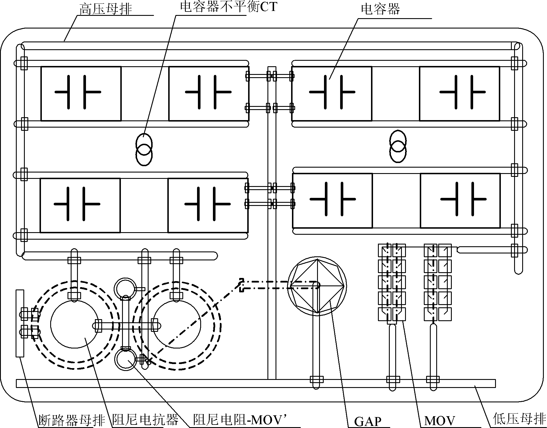
[0042] The top view of the series compensation capacitor platform of Scheme 2 is as follows: image 3 As shown, among them, the difference from scheme 1 is:

[0043] The low-voltage busbars are arranged on the capacitor platform in an inverted T shape; the high-voltage busbars are arranged on the capacitor platform in the shape of a cover with hooks; the capacitor banks connected by double H bridges are arranged symmetrically on both sides of the inverted T-shaped low-voltage busbars; One end of the group is connected to the high-voltage busbar, and the other end is connected to the low-voltage busbar.

[0044] The damping device is arranged between the high-voltage busbar and the low-voltage busbar on the horizontal center line, on on...


PUM


Abstract

A capacitor platform for a series compensation device comprises at least one capacitor group, at least one metal oxide varistor, at least one spark gap, and at least one damping device. The capacitor platform is made of a steel structure and is placed horizontally. The capacitor group is disposed respectively opposite to the damping device, the spark gap, and the metal oxide varistor; the damping device, the spark gap, and the metal oxide varistor are disposed at the same side of the capacitor platform; the damping device is disposed above the spark gap and the metal oxide varistor or is mirrored. Alternatively, the capacitor group is disposed above the damping device, the spark gap, and the metal oxide varistor or is mirrored; the damping device is disposed respectively opposite to the spark gap and the metal oxide varistor. The capacitor platform has a compact layout, rational structure, full consideration on major device insulation, and cooperation on overall layout of major devices, and places the devices rationally with balanced force, thereby achieving the object of rational utilization of the platform space.

Description

technical field [0001] The invention belongs to the field of flexible alternating current transmission (FACTS) of electric power system, and specifically relates to a capacitor platform of a series compensation device, which is especially suitable for a fixed series capacitor compensation device (FSC), especially a fixed series capacitor compensation device with a voltage level of 750kV and 1000kV. Background technique [0002] There are great differences in the geographical distribution of primary energy and power loads around the world, and this difference is particularly prominent in my country. With economic development, the contradiction between supply and demand between energy supply and power consumption is becoming more and more serious. Long-distance, large-capacity, and cross-regional power transmission can effectively alleviate the contradiction between power supply and demand, which has become one of the most important features of modern power systems. Power tran...

Claims


Application Information

Patent Timeline
Patent Type & Authority Patents(China)
IPC IPC(8): H02J3/18H02B1/04H02B1/20
CPCH02J3/1807Y02E40/30H02J3/18
Inventor 武守远赵波金雪芬李庆光戴朝波魏东华宋宏佺
Owner CHINA EPRI SCIENCE & TECHNOLOGY CO LTD
Why Eureka
Try Eureka