Regenerative brake control device

A technology of regenerative braking and control devices, applied in the direction of regenerative braking, control devices, mechanical brake transmission devices, etc., can solve the problems of difficult to deal with various needs and cannot change the operation volume, so as to reduce the operating load and sensitive control Effect

Active Publication Date: 2014-07-02
MITSUBISHI MOTORS CORP
View PDF6 Cites 9 Cited by
  • Summary
  • Abstract
  • Description
  • Claims
  • Application Information

AI Technical Summary

Problems solved by technology

[0005] However, in Japanese Utility Model Patent No. 2579650, the operation amount of the operation member required to change the regenerative braking force to a pr

Method used


Image

  • Regenerative brake control device
  • Regenerative brake control device
  • Regenerative brake control device

Examples


Embodiment Construction

[0029] Hereinafter, exemplary embodiments according to the present invention will be described in detail with reference to the accompanying drawings. However, unless otherwise specified, note that dimensions, materials, shapes, relative arrangements, etc. of components described in the exemplary embodiments do not limit the scope of the present invention, but are for illustrative purposes only.

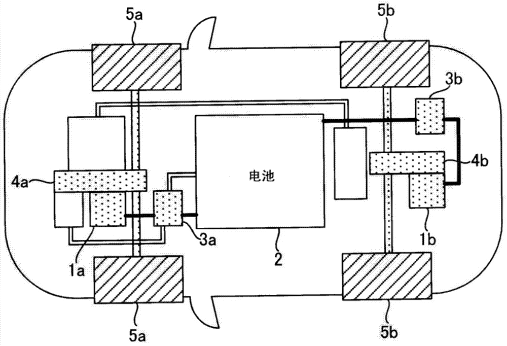
[0030] figure 1 is a schematic diagram showing the entire configuration of an electric vehicle (hereinafter, referred to as "vehicle") on which the regenerative braking control device according to the present embodiment is mounted. refer to figure 1 , as energy sources for running, a front engine 1a and a rear engine 1b as electric motors are provided on the front and rear sides, respectively (hereinafter, the front engine 1a and the rear engine 1b may be collectively referred to as "engine 1"). A battery 2 that stores DC power in advance is mounted on the vehicle. Electric energy ...


PUM


Abstract

A regenerative brake control device for an electric-powered vehicle includes a first regenerative braking force setting unit that is operated by a predetermined number of times so as to change a setting of the regenerative brake control device from a normal regeneration level to a predetermined regeneration level, and a second regenerative braking force setting unit that is operated by a number of times that is greater than the predetermined number of times so as to change the setting of the regenerative brake control device from the normal regeneration level to the predetermined regeneration level.

Description

technical field [0001] The present invention relates to the technical field of a regenerative braking control device for an electric vehicle, which obtains regenerative braking force by regeneratively driving an electric motor as a running energy. Background technique [0002] Known electric vehicles run by driving an electric motor as a running energy source using electric energy stored in a battery (notably, an electric vehicle in this application is considered to include an electric vehicle having an electric motor as a running energy source and other than Hybrid electric vehicles that have an internal combustion engine in addition to an electric motor). In such electric vehicles, during deceleration, braking force (regenerative braking force) is obtained by regeneratively driving the electric motor, and the kinetic energy of the vehicle is accumulated as electric energy through the generation of regenerative energy. From the viewpoint of energy efficiency, it is desired...

Claims


Application Information

Patent Timeline
IPC IPC(8): B60L7/10
CPCB60L15/2009B60L7/18Y02T10/7283B60L15/2045B60K6/48B60K6/52B60T1/10B60T7/22B60W30/18127B60L2240/423B60L2250/24B60T2201/022B60W2540/16F16H2059/0247B60T2270/60B60W30/14B60W30/143Y02T10/62Y02T10/64Y02T10/72B60L50/00B60L7/10B60T8/17B60T11/08
Inventor 林邦繁
Owner MITSUBISHI MOTORS CORP
Why Eureka
Try Eureka