An automatic control system for the stability of temporary cable erection brackets

An automatic control system and temporary cable technology, applied in the direction of fluid pressure actuation system safety, fluid pressure actuation system components, pipe supports, etc., can solve the problems of heavy connecting hooks, slow tightening speed, and affecting construction progress, etc., to achieve Good equipment versatility, accurate tension control, simple and convenient installation

Active Publication Date: 2016-05-25
STATE GRID CORP OF CHINA +2
View PDF6 Cites 0 Cited by
  • Summary
  • Abstract
  • Description
  • Claims
  • Application Information

AI Technical Summary

Problems solved by technology

The currently used aerial laying of cables is generally realized by setting up cable erection brackets, but the existing cable erection brackets are directly fixed on the ground through multiple cable-stayed wires and ground anchors. Loosening and offsetting the erection bracket, but these changes are difficult to detect, posing serious safety hazards, and it takes a lot of time and manpower to adjust and fix the cable erection bracket during the erection process, which seriously affects the construction progress
[0003] During the construction of high-voltage transmission circuits, it is necessary to cross the transmission lines in use, railways, traffic arterial roads, etc., and to erect temporary arched frames. Due to the large span of the frames, many cable-stayed wires are required to fix them. To ensure safety, the number of cable-stayed wires Many, large tension; after the whole frame is assumed to be completed, the main diagonal stay wire needs to be tightened in the fixing stage. Now the chain is tightened by the reverse chain. The conventional reverse chain is too long, the tightening speed is slow, and the connecting hook It is quite bulky and inconvenient to use. The function of using custom-made uplink equipment is single and the utilization rate of equipment resources is low.
[0004] After the cable-stayed wires of the above-mentioned brackets are installed, there are few personnel to check and maintain them. They have no intuitive understanding of the status of the entire bracket. The staff do not know how much tension is required for each cable-stayed wire, which has buried the safety and stability of the brackets. safety hazard

Method used


Image

  • An automatic control system for the stability of temporary cable erection brackets
  • An automatic control system for the stability of temporary cable erection brackets
  • An automatic control system for the stability of temporary cable erection brackets

Examples


Embodiment 1

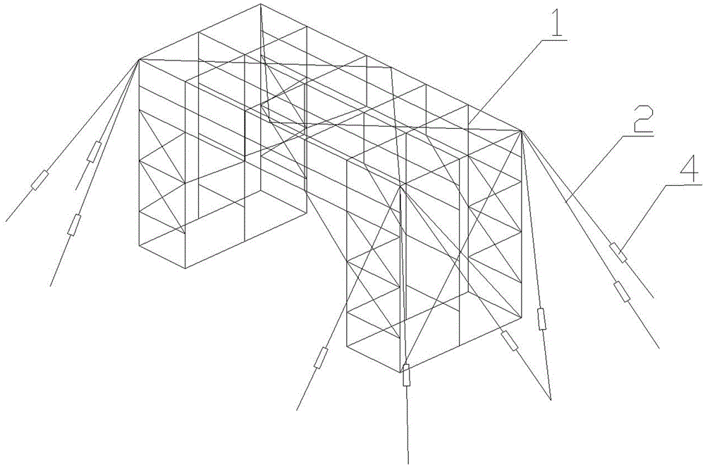
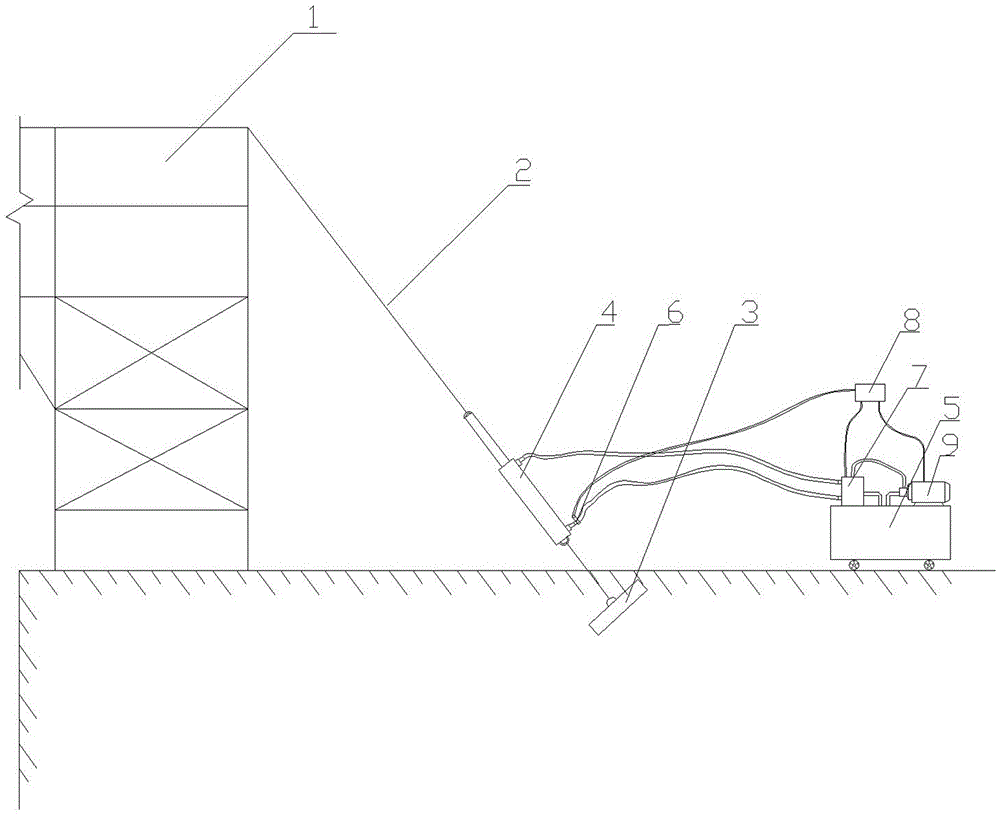
[0028] as attached Figure 1-3 As shown, a temporary cable erection support stability automatic control system, which includes a support body, a hydraulic system and a PLC control system, wherein:

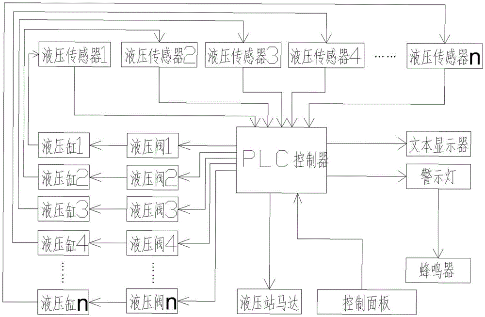
[0029] The support body includes a square arch body 1, a cable stay 2 and a ground anchor 3, the cable stay 2 is connected to the top corner of the square arch frame 1, and the cable stay 2 is connected to the ground through the ground anchor 3. Fixed; the hydraulic system includes a hydraulic station 5 and a hydraulic cylinder 4 arranged between the stay wire 2 and the ground anchor 3, and the hydraulic cylinder 4 is connected to the hydraulic station 5 through a hydraulic valve 7; the The PLC control system comprises a PLC controller 8, an alarm and a hydraulic sensor 6 arranged on the hydraulic cylinder 4; the hydraulic sensor 6 is connected to the input end of the PLC controller, and the alarm, hydraulic valve 7 and hydraulic station motor 9 are respectively connected to the o...


PUM


Abstract

The invention relates to a system for automatically controlling the stability of a temporary cable erection support. The system comprises a support body, a hydraulic system and a PLC control system, all inclined pulling wires are connected through the hydraulic system so that a linkage joint adjustment effect can be achieved, then the tensile force of all the inclined pulling wires can be independently or simultaneously controlled through the PLC control system, the system is easy and convenient to install, the inclined pulling wires and ground anchors can be connected only through a hydraulic cylinder, the hydraulic cylinder is controlled to stretch or retract by a hydraulic valve so that the tensile force of the inclined pulling wires can be adjusted, the responding speed is high, the tensile force is accurately controlled, and the whole set of equipment can be installed fast.

Description

technical field [0001] The invention relates to the field of cable support erection, in particular to an automatic control system for the stability of a temporary cable erection support. Background technique [0002] At present, temporary cables need to be erected in almost all construction sites. Temporary power cables are generally laid in two ways: buried or overhead. Due to the natural environment of the site, buried laying is not suitable for all situations, and The overhead cable laying method is favored by the majority of power companies due to its wide application range. The currently used aerial laying of cables is generally realized by setting up cable erection brackets, but the existing cable erection brackets are directly fixed on the ground through multiple cable-stayed wires and ground anchors. Loosening and offsetting the erection bracket, but these changes are difficult to be found, and there are serious safety hazards, and it takes a lot of time and manpowe...

Claims


Application Information

Patent Timeline
Patent Type & Authority Patents(China)
IPC IPC(8): F15B21/02F15B20/00F16G11/12F16L3/24
Inventor 冯环张慧君董天玉李占凯
Owner STATE GRID CORP OF CHINA
Why Eureka
Try Eureka