Anchor and anchor nut thereof

A technology of anchor rods and nuts, applied in the direction of nuts, screws, threaded fasteners, etc., to achieve the effect of simplified measures

Inactive Publication Date: 2014-07-02
阿特拉斯·科普柯塞科罗克股份公司
View PDF6 Cites 6 Cited by
  • Summary
  • Abstract
  • Description
  • Claims
  • Application Information

AI Technical Summary

Problems solved by technology

[0007] The problem with the known bolts described above is that in order to achieve the rotation of the bolt body (which can be a solid rod or

Method used


Image

  • Anchor and anchor nut thereof
  • Anchor and anchor nut thereof
  • Anchor and anchor nut thereof

Examples


Embodiment Construction

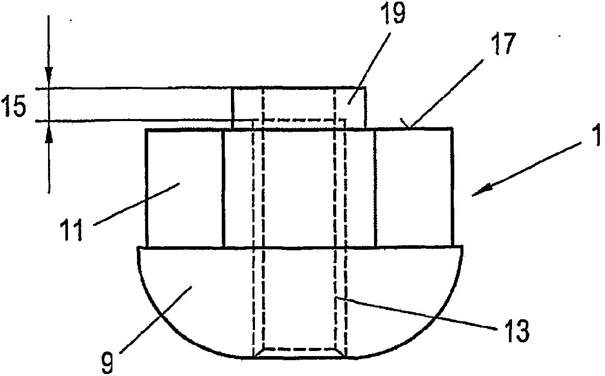
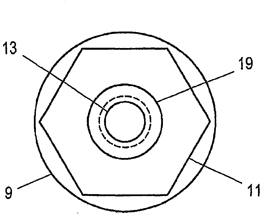
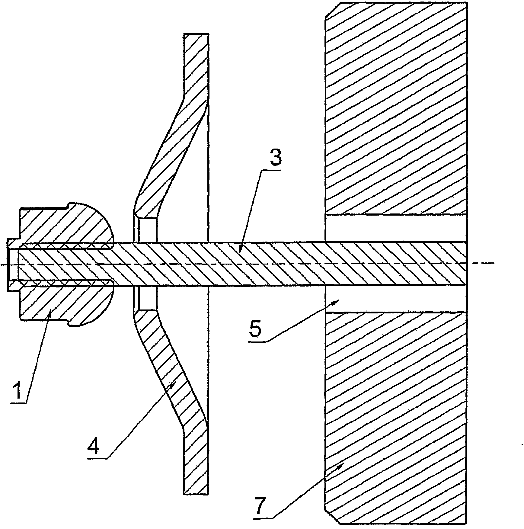
[0019] It is known per se from the prior art that when installing anchors, for example of the bonded or mortar type, but also in the case of expansion-shell anchors, the anchor body 3 The outer end (this outer end protrudes from the foundation 7 on which the anchor rod is installed) is sleeved with an anchor backing plate 4, and the anchor backing plate is then pressed onto the foundation 7 by using an anchor nut 1.

[0020] In the present invention, the anchor nut 1 is also used to rotate the anchor shank 3, when the anchor shank is screwed in for the purpose that, with its front end received in the borehole 5, it will be placed A binder sleeve or a mortar sleeve at the inner end of the borehole 5 opens to release the binder / mortar and mix it, but it can also be used when using grooved wedge bolts, sliding wedge bolts, In the case of an expansion shell bolt or the like, an expansion body arranged on the front end of the bolt body received in the borehole is adjusted to achiev...


PUM


Abstract

Anchor has a rod (3) of the anchor, which must rotate as the anchor is installed, a board (4) of the anchor and an anchor nut (1). Thread of the anchor nut (1) is fit to the thread of the anchor rod (3) only on a part of the threaded hole (13). Therefore the anchor nut (1) may be screwed onto the rod (3) only a bit further and may be used to rotate the rod (3) as the anchor is installed before a certain torque is applied. As soon as the rod (3) is fixed in the drilled hole by means of glue, mortar or spacing, when the anchor nut (1) rotates relative to the rod (3), it forms solid thread in the threaded hole (13), so that the anchor nut (1) may finally be screwed onto the rod (3) so that it fixes the anchor board (4) in its final position on the base (7). ^ EFFECT: simplified design and assembly of fixtures.

Description

[0001] This application is based on the application number 200880007945.9 (international application number is PCT / AT2008 / 000013), the application date is January 17, 2008, and the invention title is "anchor and the anchor nut used therein". case application. technical field [0002] The invention relates to an anchor rod. In particular, the invention relates to anchors whose body must be rotated when loading (installing) the anchor, such as is done for bonded anchors, anchors fixed by mortar or expansion joints. This is the case with shell bolts. Background technique [0003] When installing the bonded anchor, it should be carried out as follows: first drill a hole on the basis of the anchor to be installed. One or more sleeves containing adhesive are then inserted into the borehole, either by pushing the sleeves into the borehole with a pressure rod or with compressed air. These sleeves usually contain a two-component adhesive, the components of which are spatially sepa...

Claims


Application Information

Patent Timeline
IPC IPC(8): F16B37/00F16B13/14F16B31/02
CPCF16B31/02F16B13/141F16B13/14
Inventor M·迈德尔
Owner 阿特拉斯·科普柯塞科罗克股份公司
Why Eureka
Try Eureka