Novel LED lamp strip and liquid crystal module provided with same

A technology for LED light strips and liquid crystal modules, which is applied to the parts of lighting devices, lighting and heating equipment, instruments, etc., can solve the problem of vignetting quality, the LED light-emitting area cannot be completely covered, and it cannot meet the requirements of narrow borders and no borders. and other problems to achieve the effect of meeting the design requirements

Active Publication Date: 2014-07-02
L&T DISPLAY TECH FUJIAN
View PDF10 Cites 3 Cited by
  • Summary
  • Abstract
  • Description
  • Claims
  • Application Information

AI Technical Summary

Problems solved by technology

[0002] Existing conventional LED liquid crystal displays, when using the backlight design scheme of side-incidence type, such as Figure 1~2 As shown, the terminal 13 (Connector) of the existing LED light bar 1 is in the same straight line as the LED 12. Since the effective maximum luminous angle of each LED 12 is limited, and the size of the terminal 13 is 7.9mm, it needs to occupy a certain space. ; When the distance between the light-emitting area of ​​the light guide plate and the edge of the back shell is less than about 5mm, the LED light-emitting area of ​​the existing LED light bar cannot completely cover the visible area of ​​the LCD panel, and quality problems such as insurmountable vignetting will occur at the edge
At present, liquid crystal modules are more and more pursuing the effect of narrow frame and no frame, but the design structure of the existing LED light bar hinders the improvement of the frame structure, and cannot meet the technical requirements of narrow frame and no frame

Method used


Image

  • Novel LED lamp strip and liquid crystal module provided with same
  • Novel LED lamp strip and liquid crystal module provided with same
  • Novel LED lamp strip and liquid crystal module provided with same

Examples


Embodiment Construction

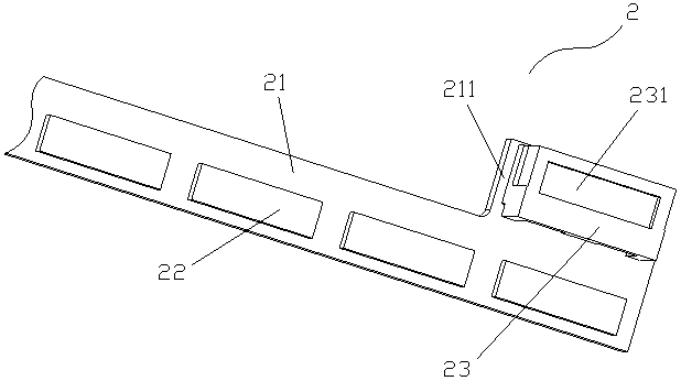
[0017] Such as image 3 As shown, a new type of LED light bar includes a strip-shaped PCB board 21, and the surface of the PCB board 21 is packaged with a plurality of equally spaced LEDs 22 along its length direction. The terminal side of the PCB board 21 A connecting portion 211 extends from the portion along its width direction. The connecting portion 211 of the PCB 21 is provided with a connecting terminal 23 on its surface.

[0018] In this embodiment, in order to improve the heat dissipation effect, the PCB board 21 is an aluminum substrate; the size of the connecting terminal 23 is 7.9 mm.

[0019] Such as Figure 3~5 As shown, a liquid crystal module applying the above-mentioned new type of LED light bar, including a back plate 3, a new type of LED light bar 2 and a light guide plate 4, the light guide plate 4 is arranged on the back plate 3, and the new type of LED light bar The light bar 2 is arranged on the side of the light guide plate 4, and a visible area A of ...


PUM

PropertyMeasurementUnit
sizeaaaaaaaaaa

Abstract

The invention relates to a novel LED lamp strip and a liquid crystal module provided with the same. The novel LED lamp strip comprises a strip-shaped PCB, a plurality of LEDs distributed at intervals are arranged on the surface of the PCB in the length direction of the PCB in a packaged mode, a wiring portion extends out of the side portion of the wiring end of the PCB in the width direction of the PCB, a wiring terminal is arranged on the surface of the wiring portion of the PCB, and the direction of the plug-and-pull port of the wiring terminal is perpendicular to the surface of the PCB. According to the novel LED lamp strip and the liquid crystal module provided with the same, the wiring terminal of the LED lamp strip is moved upwards, a viewing area is covered with the LEDs to the greatest extent, the narrow-bezel effect of the liquid crystal module is superlative, and design requirements of ultra-narrow-bezel models are met; in addition, the plug-and-pull direction of the wiring terminal of the LED lamp strip is changed to be perpendicular to the surfaces of the LEDs, and the overall thickness of a complete machine is not affected.

Description

technical field [0001] The invention relates to a novel LED light bar and a liquid crystal module using the same, and belongs to the field of liquid crystal display / liquid crystal TV manufacturing. Background technique [0002] Existing conventional LED liquid crystal displays, when using the backlight design scheme of side-incidence type, such as Figure 1~2 As shown, the terminal 13 (Connector) of the existing LED light bar 1 is in the same straight line as the LED 12. Since the effective maximum luminous angle of each LED 12 is limited, and the size of the terminal 13 is 7.9mm, it needs to occupy a certain space. ; When the distance between the light-emitting area of ​​the light guide plate and the edge of the back shell is less than about 5mm, the LED light-emitting area of ​​the existing LED light bar cannot completely cover the visible area of ​​the LCD panel, and quality problems such as insurmountable vignetting will occur at the edge . At present, liquid crystal mo...

Claims


Application Information

Patent Timeline
Patent Type & Authority Applications(China)
IPC IPC(8): F21S8/00F21V19/00F21V23/06G02F1/13357F21Y101/02
Inventor 俞明捷陈俊勤
Owner L&T DISPLAY TECH FUJIAN
Why Eureka
Try Eureka