
An energy-saving device for external circulation heat exchange in a communication room

A communication machine room and energy-saving device technology, which is applied in the direction of household heating, heating methods, lighting and heating equipment, etc., can solve the problems of low efficiency, heavy maintenance workload, insulation aging and damage, etc., and achieve obvious energy-saving effect and high degree of automation , the effect of strong adaptive ability

Active Publication Date: 2016-03-16
桑永礼
View PDF4 Cites 0 Cited by
  • Summary
  • Abstract
  • Description
  • Claims
  • Application Information

AI Technical Summary

Problems solved by technology

[0005] One is low efficiency: Due to the moisture-proof and dust-proof requirements of the communication room, the existing communication ventilation equipment generally adopts two-stage filtration and absorption, and two-stage filtration is used. Although the dust-proof and moisture-proof problems are solved to a certain extent, but It also brought about a fundamental problem, that is, after being blocked by the two-stage filter, the actual amount of cold air introduced by the ventilation equipment in the computer room is small, the heat carried by the fresh air is seriously insufficient, and the use effect is not obvious
Second, the maintenance workload is heavy: the change of air quality, ambient temperature and temperature difference is the key period for adjusting the temperature of the computer room. In the three seasons of spring, autumn and winter in the area north of the Yangtze River and Huaihe River in my country, the phenomenon of blowing sand, floating dust and floating flocs is common.
During the operation of the ventilation motor in the computer room, the blowing sand, floating dust, and floating lint often cause the phenomenon of "dirty blockage" in the short-term operation of the two-stage filter
According to the actual maintenance experience, the ventilation and energy-saving equipment in the general computer room will be completely dirty and blocked after running for about half a month, and the two-stage filter needs to be replaced once. There are hundreds of sites in a city, and the maintenance workload can be imagined
The third is high operating costs: replacing the two-stage filter screen once every half a month brings at least two cost problems: a large number of filter screen spare parts need to be configured, which increases the cost very high; a large amount of maintenance manpower, material resources, and transportation tools need to be invested increase operating costs
The fourth is that it is actually in a state of abandonment: in the current situation where the network maintenance funds are limited and the maintenance personnel and transportation equipment are relatively tight, it is impossible to replace the two-stage filter once every half a month
This has led our communication companies to invest a lot of money in the construction of thousands of ventilation equipment in the communication room, but the filter screen cannot be replaced in time. What kind of "criminal" waste is it to consume electricity
Fifth, there is a potential fire accident: when the operating temperature of the external environment is set, even if the filter screen of the ventilation equipment in the communication room is in a "dirty and blocked" state, the ventilation motor will continue to run
We know that the ventilation motor itself is cooled by circulating cold air. In this state, there is basically no cold air flowing through the motor, which will cause the coil of the ventilation motor to continue to heat up for a long time, which is prone to insulation aging and damage, and even causes short-circuit fire accidents. There are obvious hidden dangers of fire safety accidents

Method used


Image

  • An energy-saving device for external circulation heat exchange in a communication room
  • An energy-saving device for external circulation heat exchange in a communication room
  • An energy-saving device for external circulation heat exchange in a communication room

Examples


Embodiment Construction

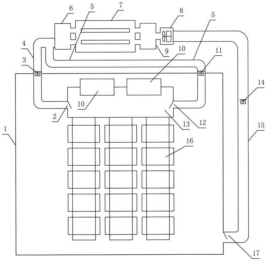
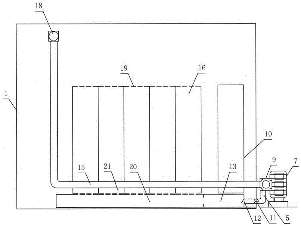
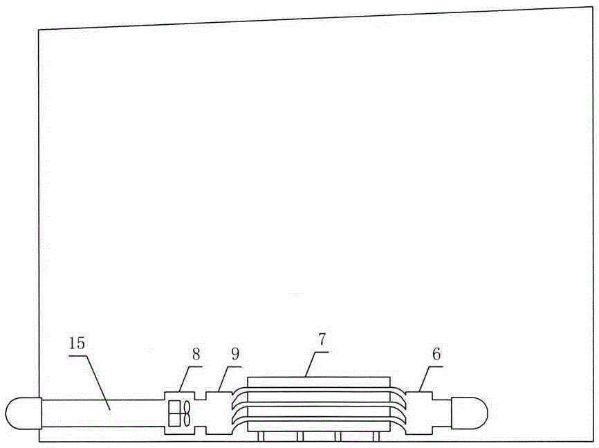
[0056] Figure 1-4 The rear outer side of the machine room 1 shown in the figure is provided with a heat exchanger 7, and the frame 33 of the heat exchanger is provided with a cooling radiating pipe 34, and the left side of the heat exchanger is provided with a cold wind collecting box 6, and the outlet of the cold wind collecting box is provided with There are left cold air passage 4, right cold air passage 5, left cold air passage is equipped with left afterburner fan 3, right cold air passage is provided with right afterburner fan 11, and communication network equipment 16 is installed in the machine room, and the communication network equipment is arranged and installed in sequence In the computer room, an air conditioner 10 is provided on the rear side of the communication network equipment, a floor trough is provided at the bottom of the air conditioner, a cold air channel slot 20 is provided at the bottom of the communication network equipment, and a cold air inlet net i...


PUM


Abstract

The invention discloses an outer circulation heat exchange energy-saving device for a communication equipment room. The device is characterized in that a heat exchanger is arranged outside the back of the equipment room, a cooling pipeline is arranged in a frame of the heat exchanger, a cold air collection box is arranged on the left of the heat exchanger, a left cold air channel and a right cold air channel are arranged on an air outlet of the cold air collection box, communication network equipment is arranged in the equipment room, an air-conditioner is arranged at back of the communication network equipment, a ground groove is formed in the bottom end of the air-conditioner, cold air channel grooves are formed in the bottom end of the communication network equipment, cold air inlet net plates are arranged at the upper ends of the cold air channel grooves, cold air outlet holes are formed in the upper end of the communication network equipment, a cold air tank is arranged in the ground groove of the bottom end of the air-conditioner, the cold air channel grooves are sequentially connected with the cold air tank, an exhaust fan is arranged at the right end of a hot air box, an exhaust pipeline is installed on the right of the exhaust fan, an exhaust inlet of the exhaust pipeline is installed in the equipment room, a temperature controller is arranged in the equipment room, and an outdoor temperature sensor is arranged on the left outside of the temperature controller.

Description

technical field [0001] The invention relates to an air circulation device for a communication machine room, specifically an energy-saving device for external circulation heat exchange in a communication machine room. Background technique [0002] With the progress of the society and the rapid development of the communication network business, the communication network sites and IDC communication rooms in various places have been "scattered", and in order to improve the quality of communication, there is a trend of encryption and expansion, and the energy consumption of network equipment operated at the same time also showed a straight-line upward trend. Therefore, how to save energy and reduce consumption under the premise of ensuring network quality, reduce operators' network operation and maintenance costs, and realize "low-cost, high-efficiency" operation is the biggest problem facing every operator. [0003] At present, the existing communication equipment room adopts a...

Claims


Application Information

Patent Timeline
Patent Type & Authority Patents(China)
IPC IPC(8): F24F5/00
Inventor 桑永礼
Owner 桑永礼
Learn More