Remote sensing ground simulation test stand

A technology of ground simulation and test rack, applied in the direction of measuring devices, measuring instrument components, instruments, etc., can solve the problems of large dumping force, personal injury, poor stability, etc., and achieve the effect of stable rack body and labor-saving control.

Active Publication Date: 2016-08-17
徐州新南湖科技有限公司
View PDF9 Cites 0 Cited by
  • Summary
  • Abstract
  • Description
  • Claims
  • Application Information

AI Technical Summary

Problems solved by technology

However, there are serious problems in this method. First, the inclination angle of the rod body is difficult to control, and the stability is very poor.
Furthermore, since the height of the pole body is 6-8 meters, when there is a crosswind in the test environment, it is difficult for people to stabilize the pole body, so it is difficult to stabilize the image
Finally, this method has great potential safety hazards for the testers. When there is a crosswind, for a high pole with a height of 6-8 meters, the tipping force is very strong, and it is easy to cause serious personal injury when it hits someone.

Method used


Image

  • Remote sensing ground simulation test stand
  • Remote sensing ground simulation test stand
  • Remote sensing ground simulation test stand

Examples


Embodiment Construction

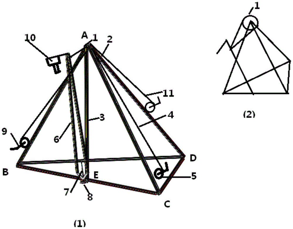
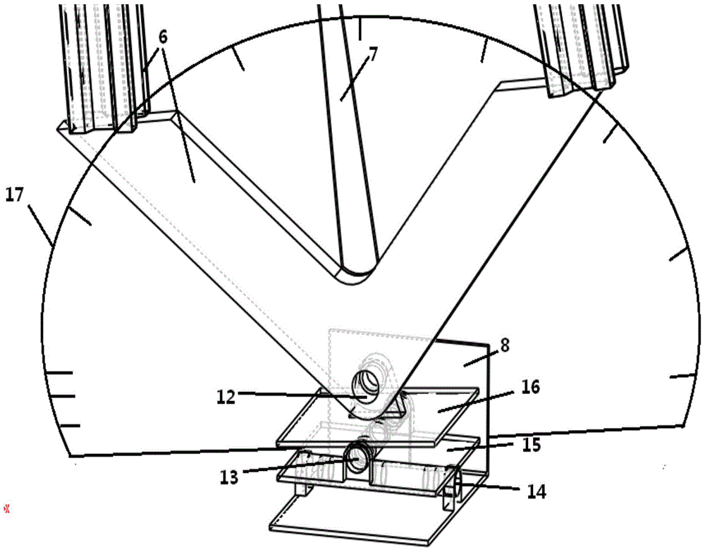
[0030] see figure 2 It can be seen that the frame body 2 of one embodiment of the present invention is a triangular pyramid truss structure including a vertical vertical surface, ABCD is the apex of the truss structure, and the truss structure is made of high-strength and lightweight aluminum. Quick connectors are used between them to ensure fast assembly and disassembly of the frame body; the vertical column 3 of the vertical surface ABC of the triangular pyramid truss body is used as the pull rope guide pulley 1 at the top of the triangular pyramid, and the chassis installation carrier for adjusting the initial posture of the swing rod; 6 It is an inverted L-shaped swing rod, and its structure is a vertical rod and a horizontal rod fixed on the vertical rod. The horizontal rod and the vertical rod form an angle of 90 degrees. The swing rod structure can be a single rod structure or a image 3 4 is a steel wire traction rope that pulls and controls the 6 angles of the pendul...


PUM


Abstract

The invention discloses a remote sensing ground simulation test frame and relates to the field of erection and simulation of positions and motion states of ground imaging sensors. The remote sensing ground simulation test frame is characterized by comprising a triangular-pyramid-shaped truss body structure, a center pillar of a triangular-pyramid-shaped truss body perpendicular vertical face ABC, an inverted-L-shaped swing rod, a swing rod traction angle indicating needle, a swing rod initial position adjusting base plate and an imaging sensor, wherein a pulley is arranged on the top of the truss body, the position and angle of the inverted-L-shaped swing rod are controlled through a steel wire traction rope, one end of the steel wire rope is connected to the position lower than the top end of the inverted-L-shaped swing rod, the steel wire rope surrounds the pulley to be twisted to a hand-cranking traction rope winch which is used for winding and unwinding the traction rope, the swing rod traction angel indicating needle is matched with the angle indicating base plate and reads the angle of the swing rod, the imaging sensor is installed on the cross rod of the inverted-L-shaped swing rod, and the inverted-L-shaped swing rod can swing leftwards and rightwards around a rotary middle shaft of the adjusting base plate. According to the remote sensing ground simulation test frame, the truss body is stable, the angle of the swing rod is readable and adjustable, and the angle of the swing rod is safely controlled in a labor-saving mode.

Description

Technical field: [0001] The invention relates to a simulation device for satellite remote sensing ground imaging, in particular to the field of erection simulation of the position and motion state of ground imaging sensors. Background technique: [0002] The imaging characteristics of space satellites on ground materials must be calculated in advance and tested in detail when designing satellite imaging sensors. However, due to the high cost of satellite launch, simple mobile ground tests need to be carried out on various ground environments before the scheme is fully formulated. During the test, the angle of the imaging sensor relative to the target to be tested needs to be controlled. When performing simple tests on the radiation characteristics of turf, bare ground, etc., the existing literature basically uses an inverted L-shaped rod body, and the imaging sensor is installed on the crossbar of the inverted L-shaped rod body. Hold the rod body with your hands to maintain...

Claims


Application Information

Patent Timeline
Patent Type & Authority Patents(China)
IPC IPC(8): G01D11/30
Inventor 刘晓民
Owner 徐州新南湖科技有限公司
Why Eureka
Try Eureka