Built-in rotation speed measurement device of supercharger
A technology of speed measurement and supercharger, which is applied to measurement devices, linear/angular velocity measurement, speed/acceleration/shock measurement, etc., can solve the problems of low measurement accuracy, unsuitable for long-term use, inconvenient installation of measurement devices, etc. Simple, reliable results
- Summary
- Abstract
- Description
- Claims
- Application Information
AI Technical Summary
Problems solved by technology
Method used
Image
Examples
Embodiment 1
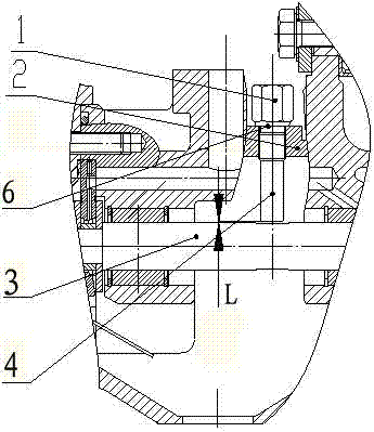
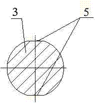
[0020] like figure 1 As shown, a built-in speed measurement device for a supercharger includes a speed sensor 1, a bearing body 2, and a speed sensor 3 is a rotating shaft. The speed sensor 1 is provided with a speed sensor center 4, and the speed sensor 1 is connected to the bearing body 2. A positioning plane 6 is set at the position, and the bearing body 2 is closely positioned through the positioning plane 6, and a detection platform 5 is set on the rotational speed test piece 3 (such as figure 2 ), the detection platform 5 is set on two symmetrical planes on both sides of the rotating shaft, the speed sensor 1 and the bearing body 2 are connected by M10 X 1 fine thread, and suspended at a certain distance above the speed tested part 3, And face the detection platform 5 on the rotational speed tested part 3, the measurement gap L between the rotational speed sensor center 4 on the rotational speed sensor 1 and the detection platform 5 is 0.5-1.2 mm.
Embodiment 2
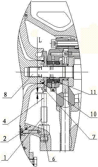
[0022] like image 3 As shown, a turbocharger built-in speed measurement device includes a speed sensor 1, a bearing body 2, a positioning plane 6 is provided at the connection between the speed sensor 1 and the bearing body 2, and the speed measured part 3 includes a shaft cover 7 and a rotating shaft 8. The shaft cover 7 is tightly fitted on the rotating shaft 8. The shaft cover 7 is sandwiched between the compressor impeller 10 and the bearing sleeve 11, and the axial clamping force ensures its firm positioning and connection. The detection platform 5 is two symmetrical The boss plane 9 (as Figure 4 ), set on the shaft cover 7, the speed sensor 1 is provided with a speed sensor center 4, the speed sensor 3 is provided with a detection platform 5, the speed sensor 1 and the bearing body 2 are connected by a fine thread of M12 X 1.25, And it is closely positioned by the positioning plane 6; and it is suspended at a certain distance above the speed tested part 3, and is faci...
PUM
 Abstract
Description
Claims
Application Information
 - R&D
- Intellectual Property
- Life Sciences
- Materials
- Tech Scout
- Unparalleled Data Quality
- Higher Quality Content
- 60% Fewer Hallucinations
Browse by: Latest US Patents, China's latest patents, Technical Efficacy Thesaurus, Application Domain, Technology Topic, Popular Technical Reports.
© 2025 PatSnap. All rights reserved.Legal|Privacy policy|Modern Slavery Act Transparency Statement|Sitemap|About US| Contact US: help@patsnap.com


