
Method for measuring material complex permittivity based on substrate integrated waveguide round resonant cavities

A substrate-integrated waveguide and complex permittivity technology, applied in measuring devices, measuring electrical variables, measuring resistance/reactance/impedance, etc., can solve problems such as inaccurate measurement, large radiation loss, and low quality factor

Active Publication Date: 2014-07-02
UNIV OF ELECTRONICS SCI & TECH OF CHINA
View PDF11 Cites 55 Cited by
  • Summary
  • Abstract
  • Description
  • Claims
  • Application Information

AI Technical Summary

Problems solved by technology

For example, researchers use microstrip ring resonators and microstrip-coupled dielectric resonators to measure the dielectric constant. However, due to the low quality factor of planar circuits such as microstrip lines and large radiation losses, the measurement is not accurate enough.

Method used


Image

  • Method for measuring material complex permittivity based on substrate integrated waveguide round resonant cavities
  • Method for measuring material complex permittivity based on substrate integrated waveguide round resonant cavities
  • Method for measuring material complex permittivity based on substrate integrated waveguide round resonant cavities

Examples


Embodiment Construction

[0043] A method for measuring the complex permittivity of a material based on a substrate-integrated waveguide circular resonator, comprising the following steps:

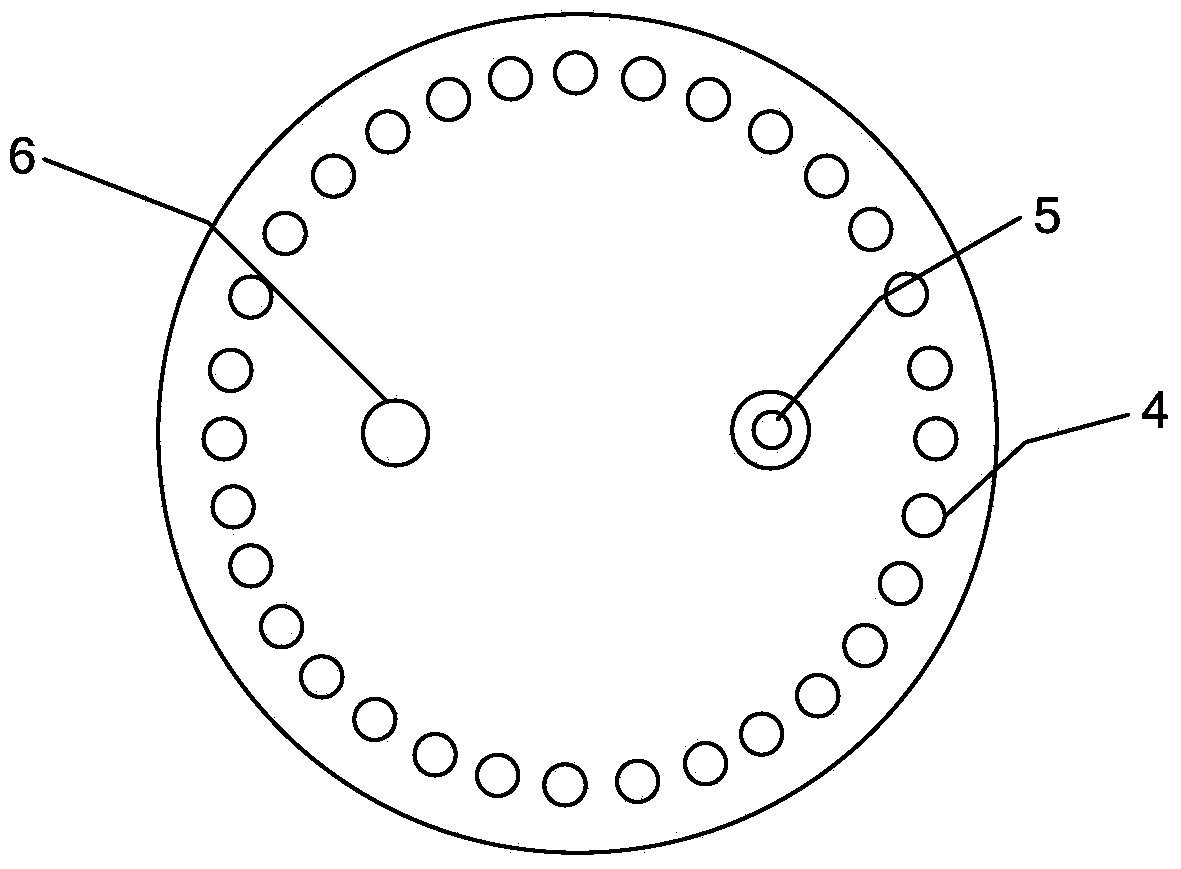
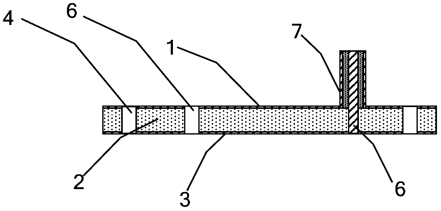
[0044] Step 1: Process substrate-integrated waveguide circular resonators with different resonant frequencies. The structure of the substrate integrated waveguide circular resonant cavity is as follows figure 1 , 2 As shown, it is processed from a dielectric plate covered with metal conductive layers on both sides, including an upper metal conductive layer 1, a dielectric layer 2, and a lower metal conductive layer 3. The dielectric layer 2 is located between the upper metal conductive layer 1 and the lower metal conductive layer. Between the conductive metal layers 3 , several metallized through holes 4 uniformly distributed in a circular shape connect the upper conductive metal layer 1 and the lower conductive metal layer 3 together. The working mode of the substrate-integrated waveguide circular resonator adop...


PUM


Abstract

The invention relates to the technical field of testing of material complex permittivity, in particular to a method for measuring material complex permittivity based on substrate integrated waveguide round resonant cavities. The method comprises the steps that firstly, the substrate integrated waveguide round resonant cavities with different resonant frequencies (work frequencies) are machined; secondly, for the substrate integrated waveguide round resonant cavities with the same resonant frequency, a sample with material identical to that of a dielectric layer 2, a standard sample with the known complex permittivity and a sample to be measured are respectively loaded, swept-frequency signals are fed respectively through a vector network analyzer, and the resonant frequencies and the quality factors of the three samples are tested; finally, simultaneous equations are established and solved, and then the complex permittivity of the sample to be measured at the work frequency of the corresponding substrate integrated waveguide round resonant cavity can be obtained. A multi-frequency-point clock test of the material complex permittivity can be completed in the mode that the substrate integrated waveguide round resonant cavities with other work frequencies are used and the same test process is repeated. The method for measuring material complex permittivity based on the substrate integrated waveguide round resonant cavities has the advantages that the sizes of the substrate integrated waveguide round resonant cavities are small, machining is convenient, and the precision of a measurement result is high.

Description

technical field [0001] The invention relates to the technical field of testing the complex dielectric constant of materials, in particular to a method for measuring the complex dielectric constant of materials based on a microwave resonant cavity. Background technique [0002] As an electromagnetic wave transmission medium, microwave materials have been widely used in various microwave fields, such as microwave circuits, communications, and radar stealth. The electromagnetic parameters of dielectric materials generally refer to complex permittivity and complex permeability, usually in the form of complex numbers ε(jω)=ε′(jω)-jε″(jω), μ(jω)=μ′(jω)- jμ″(jω) means that it is the two most basic characteristic parameters describing the interaction between materials and electromagnetic fields. Accurate understanding of electromagnetic parameter values ​​is essential for the application of microwave energy and various applications of materials in the microwave frequency range. ...

Claims


Application Information

Patent Timeline
Patent Type & Authority Applications(China)
IPC IPC(8): G01R27/26
Inventor 程钰间夏支仙黄伟娜钟熠辰樊勇
Owner UNIV OF ELECTRONICS SCI & TECH OF CHINA
Learn More