Supercharge Your Innovation With Domain-Expert AI Agents!

An optical system structure

An optical system and optical technology, applied in the direction of optics, optical components, instruments, etc., can solve the problems of lack of reach, thick thickness and large size of the optical imaging system, and achieve the effect of strong practical effect

Active Publication Date: 2017-04-12
UNION OPTECH
View PDF11 Cites 0 Cited by
  • Summary
  • Abstract
  • Description
  • Claims
  • Application Information

AI Technical Summary

Problems solved by technology

However, existing optical imaging systems cannot meet this requirement
[0006] The products in the prior art use a periscope optical imaging structure to bend the zoom optical imaging system to make the product thinner. However, due to the high resolution of the current optical imaging, the size of the imaging photoelectric element CCD / Cmos is very large. As a result, the thickness of the optical imaging system is still very thick, less than 8.0mm, or even less than 6.0mm
It cannot meet the requirements of thin camera products, especially the ultra-thin appearance of smartphones and tablets

Method used


Image

  • An optical system structure
  • An optical system structure

Examples


example 1

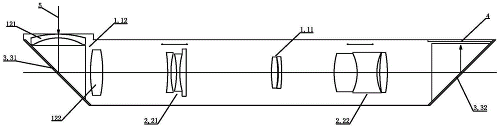
[0034] After the incident light 5 passes through the first lens 121 of the second fixed lens group 12, it is reflected by the reflective optical element 31 on the object side, and the light angle turns to 45 degrees. After passing through the second lens 122 of the second fixed lens group 12, it passes through the variable focus After passing through the first fixed lens group 11 and the focusable second movable lens group 22, the light is turned 45 degrees upward by the reflection of the reflective optical element 32 on the image side, forming an image parallel to the incident light on the optical sensing imaging surface 4 .

[0035] In this optical system structure, the zooming of the optical system is realized through the forward and backward movement on the optical axis of the first movable lens group 21 that can focus and the second movable lens group 22 that can focus. When the first moving lens group 21 moves toward the object side, the focal length becomes smaller; whe...

example 2

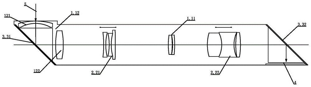
[0037] After the incident light 5 passes through the first lens 121 of the second fixed lens group 12, it is reflected by the reflective optical element 31 on the object side, and the light angle turns to 45 degrees. After passing through the second lens 122 of the second fixed lens group 12, it passes through the variable focus The first moving lens group 21, and then through the first fixed lens group 11, and the focusable second moving lens group 22, through the reflection of the image side reflective optical element 32, the light turns 45 degrees downward, parallel to the incident light The image is formed on the optical sensing imaging surface 4 .

[0038] In this optical system structure, the zooming of the optical system is realized through the forward and backward movement of the first moving lens group 21 and the second moving lens group 22 on the optical axis. When the first moving lens group 21 moves toward the object side, the focal length becomes smaller; when the...


PUM


Abstract

The invention relates to an optical system structure, which comprises a fixed lens group and a moving lens group that can be driven and moved by a driving mechanism to form an imaging system, and reflective optical elements that can reflect light are provided at both ends of the object space and the image space , an optical induction imaging surface is provided on the light emitting surface of the reflective optical element on the corresponding side of the image side. The present invention provides a reflective optical imaging system structure. The optical imaging system structure and the components configured with the camera structure, such as smart high-end mobile phones, tablet computers, card-type digital cameras, etc., can make the camera configured with the imaging system simple in structure and compact in appearance. Lightweight and practical.

Description

[0001] 【Technical field】 [0002] The invention relates to an optical system structure, in particular to a thin imaging system structure and an imaging optical lens with the structure. [0003] 【Background technique】 [0004] With the rapid development of imaging technology, the imaging quality requirements of optical camera lenses are getting higher and higher. On the one hand, the imaging resolution is required to be high, from 5 million pixels, to 8 million pixels, to 13 million pixels, to the current resolution of more than 16 million pixels. On the other hand, while the resolution of optical imaging is improved, people require an optical zoom function for high-end imaging optical systems to meet accurate focusing when shooting objects at different distances. [0005] With the improvement of imaging resolution, and the application of zoom optical system. On the other hand, another problem appeared: due to the improvement of imaging pixels, the size of imaging photoelectri...

Claims


Application Information

Patent Timeline
Patent Type & Authority Patents(China)
IPC IPC(8): G02B15/14G02B17/08
CPCG02B13/0065G02B13/009G02B15/144
Inventor 龚俊强
Owner UNION OPTECH
Features
  • R&D
  • Intellectual Property
  • Life Sciences
  • Materials
  • Tech Scout
  • Unparalleled Data Quality
  • Higher Quality Content
  • 60% Fewer Hallucinations
Learn More