Eyepiece magnification viewfinder frame

A viewfinder frame and eyepiece technology, applied in viewfinders, cameras, optics, etc., can solve the problems of unsatisfactory photos, inability to adjust parallax, etc., and achieve the effect of simple structure and easy portability

Inactive Publication Date: 2014-07-02
郑林昆
View PDF0 Cites 2 Cited by
  • Summary
  • Abstract
  • Description
  • Claims
  • Application Information

AI Technical Summary

Problems solved by technology

People with poor eyesight cannot achieve the effect of adjusting parallax, and the photos taken by the camera are often unsatisfactory.

Method used


Image

  • Eyepiece magnification viewfinder frame
  • Eyepiece magnification viewfinder frame

Examples


Embodiment Construction

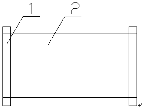
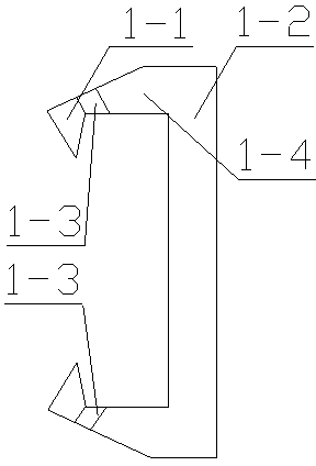
[0008] Such as figure 1 with figure 2 Shown, a kind of eyepiece magnifying viewfinder frame, it comprises two decks 1, is fixed with magnifying glass 2 between two decks, deck has vertical part 1-2 and two symmetrically arranged chucks, chucks It has a horizontal part 1-4 and a downwardly curved card point 1-1, and the joint between the card point and the horizontal part is a soft connecting strip 1-3.

[0009] When in use, the viewfinder is clamped to the eyepiece of the camera with a clip head, so that the viewfinder can be fixed, and it is convenient for the user to use a magnifying glass to enlarge the image in the eyepiece. The existence of the soft connection belt is adapted to eyepieces of different sizes.


PUM


Abstract

The invention discloses an eyepiece magnification viewfinder frame. The viewfinder frame comprises two clamp seats. A magnifying glass is fixed between two clamp seats. Each clamp seat comprises a vertical part and clamp heads located on both ends of the vertical part. Each clamp head comprises a horizontal part and a clamp tip curved inward. The joint of each clamp tip and each horizontal part is a soft connecting band. The eyepiece magnification viewfinder frame provided by the invention has the advantage of simple structure, is portable, can be arranged on different types of digital single lens reflex cameras and film single lens reflex cameras, and is convenient for a user to accurately adjust the parallax of a camera to realize a desired effect.

Description

technical field [0001] The present invention relates to a camera accessory. Background technique [0002] Cameras (digital SLRs and film cameras) are traditional cameras in the camera industry. In recent years, digital SLRs have come out one after another in developed capitalist countries and have replaced film cameras. The function of the eyepiece frame is to adjust the parallax. People with poor eyesight cannot achieve the effect of adjusting parallax, and the photos taken by the camera are often unsatisfactory. Contents of the invention [0003] The purpose of the present invention is to provide a portable eyepiece magnifying viewfinder frame. [0004] In order to achieve the above object, the following technical solution is adopted: an eyepiece magnifying viewfinder frame, characterized in that: the viewfinder frame includes two decks, a magnifying glass is fixed between the two decks, and the deck has a vertical part and a The clips at both ends of th...

Claims


Application Information

Patent Timeline
Patent Type & Authority Applications(China)
IPC IPC(8): G03B13/04
Inventor 郑林昆陇涤湘郑然袁南华刘楠
Owner 郑林昆
Why Eureka
Try Eureka