A method for calibrating motor position disturbance force

A calibration method and motor position technology, applied in the direction of electric speed/acceleration control, etc., can solve the problems of servo accuracy reduction, error, and different motion trends, etc., to achieve improved control accuracy, servo accuracy, and fewer iterations Effect

Active Publication Date: 2016-09-28
SHANGHAI MICRO ELECTRONICS EQUIP (GRP) CO LTD
View PDF7 Cites 0 Cited by
  • Summary
  • Abstract
  • Description
  • Claims
  • Application Information

AI Technical Summary

Problems solved by technology

[0004] The disadvantages of this technical solution are: (1) A single direction of motion may be driven by more than one motor, and the force output from the PID needs to be distributed to each drive motor, so adding feed-forward to the PID output will introduce errors in the force distribution process ; (2) The movement trends of the forward motion and the reverse motion are different, and taking the average of the force obtained twice as the feed-forward input will reduce the servo accuracy, such as figure 2 As shown, the solid line in the figure indicates the positive interference force, and the dotted line indicates the reverse interference force, and the trends of the two cannot be completely coincided; (3) only solves the influence of the fluctuation force caused by the uneven magnetic field; (4) the calibration process The data in the acceleration and deceleration section is not removed, so the measurement results in the acceleration and deceleration section are inaccurate

Method used


Image

  • A method for calibrating motor position disturbance force
  • A method for calibrating motor position disturbance force
  • A method for calibrating motor position disturbance force

Examples


no. 1 example

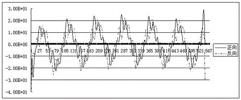
[0031] The force that the linear motor receives during the movement includes motor driving force, cable force, magnetic field wave power, stiffness damping force, etc., among which cable force, magnetic field wave power, and stiffness damping force are all related to position and are collectively referred to herein as Position interference force.

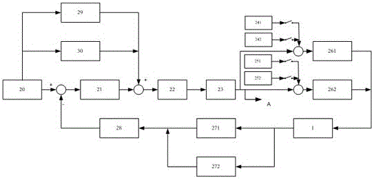
[0032] Such as image 3 As shown in the schematic diagram of the control loop of the positioning platform, the Set Point Generator 20 (SPG, Set Point Generator) is used for trajectory planning to generate sequence values ​​of acceleration, velocity and displacement, and the generated velocity feedforward coefficient 29 and acceleration feedforward coefficient 30 is added to the output of the proportional-integral-derivative controller 21 through feedforward, and acts together on the gain scheduler 22 (GS, Gain Scheduling). The output of the gain scheduler 22 acts on the gain balancer 23 (GB, Gain Balance). The gain scheduler 22 is used...

no. 2 example

[0050] Refer to the test flowchart of the position interference force meter in this embodiment Figure 8 As shown, the difference from the first embodiment is: (1) Step 1 of the embodiment is omitted, that is, there is no need to clear the original position interference force table; (2) In step 8, the boundary point The values ​​are only calculated and not compensated.

no. 3 example

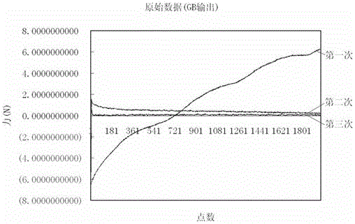
[0052] The difference between this embodiment and the first embodiment is: (1) In step 2, the start and end positions of the movement are both within the design stroke; (2) the following steps are added between step 6 and step 7, according to The position interference force table in the uniform speed section uses data fitting to calculate the position interference force table in the acceleration and deceleration section. Such as Picture 9 As shown, the fitting is carried out according to the data of the uniform speed section (represented by the circle in the figure) (represented by the solid line in the figure), and it extends to the acceleration and deceleration section according to the trend of the fitted graph. The point represented by the five-pointed star in the figure is based on the fitting graph Calculated by the trend.


PUM


Abstract

A motor position disturbance force calibration method comprises obtaining position disturbance force tables of each motor through testing offline; and adding the position disturbance force tables to the corresponding motor through feedforward to counteract the position disturbance force undertaken by the motor, wherein the position disturbance force table comprises a position disturbance force positive table and a position disturbance force negative table which are corresponding to the motion direction of the motor. The position disturbance force tables are added to the motor through feedforward directly, thereby preventing errors caused in the process that the position disturbance force tables are added to the PID output through the feedforward, and then force is allocated to each drive motor; and each motor has one position disturbance force positive table and one position disturbance force negative table, so that when the motor is moving positively and negatively, the respective position disturbance force table is utilized, and the control precision is improved.

Description

Technical field [0001] The invention relates to the field of precise positioning of a motion table, in particular to a method for calibrating the position interference force of a motor. Background technique [0002] The workpiece stage in the field of lithography machine is a high-precision positioning motion stage (hereinafter referred to as the positioning stage), which requires large-stroke and high-precision motion. The servo accuracy is generally at the nanometer level. Therefore, it has high requirements on the executive motor. Magnet linear motor. In order to improve the motion control accuracy of the positioning table, air-floating guide rails are generally used to reduce friction, and cooling water is used to reduce the heat of the motor. In addition, there are various cables on the positioning table to transmit data signals. These air pipes, water pipes and cables have a certain interference force on the motion control accuracy of the positioning table, and the interfe...

Claims


Application Information

Patent Timeline
Patent Type & Authority Patents(China)
IPC IPC(8): G05D13/62
Inventor 唐彩红
Owner SHANGHAI MICRO ELECTRONICS EQUIP (GRP) CO LTD
Why Eureka
Try Eureka