
Thin film transistor and array substrate

A technology of thin film transistors and array substrates is applied in the field of liquid crystal display, which can solve the problems of reducing the display brightness, uneven distribution and difference of liquid crystal display panels, and achieve the effect of improving the display quality of the picture and the uniform distribution of capacitance.

Active Publication Date: 2014-07-02
TCL CHINA STAR OPTOELECTRONICS TECH CO LTD
View PDF3 Cites 0 Cited by
  • Summary
  • Abstract
  • Description
  • Claims
  • Application Information

AI Technical Summary

Problems solved by technology

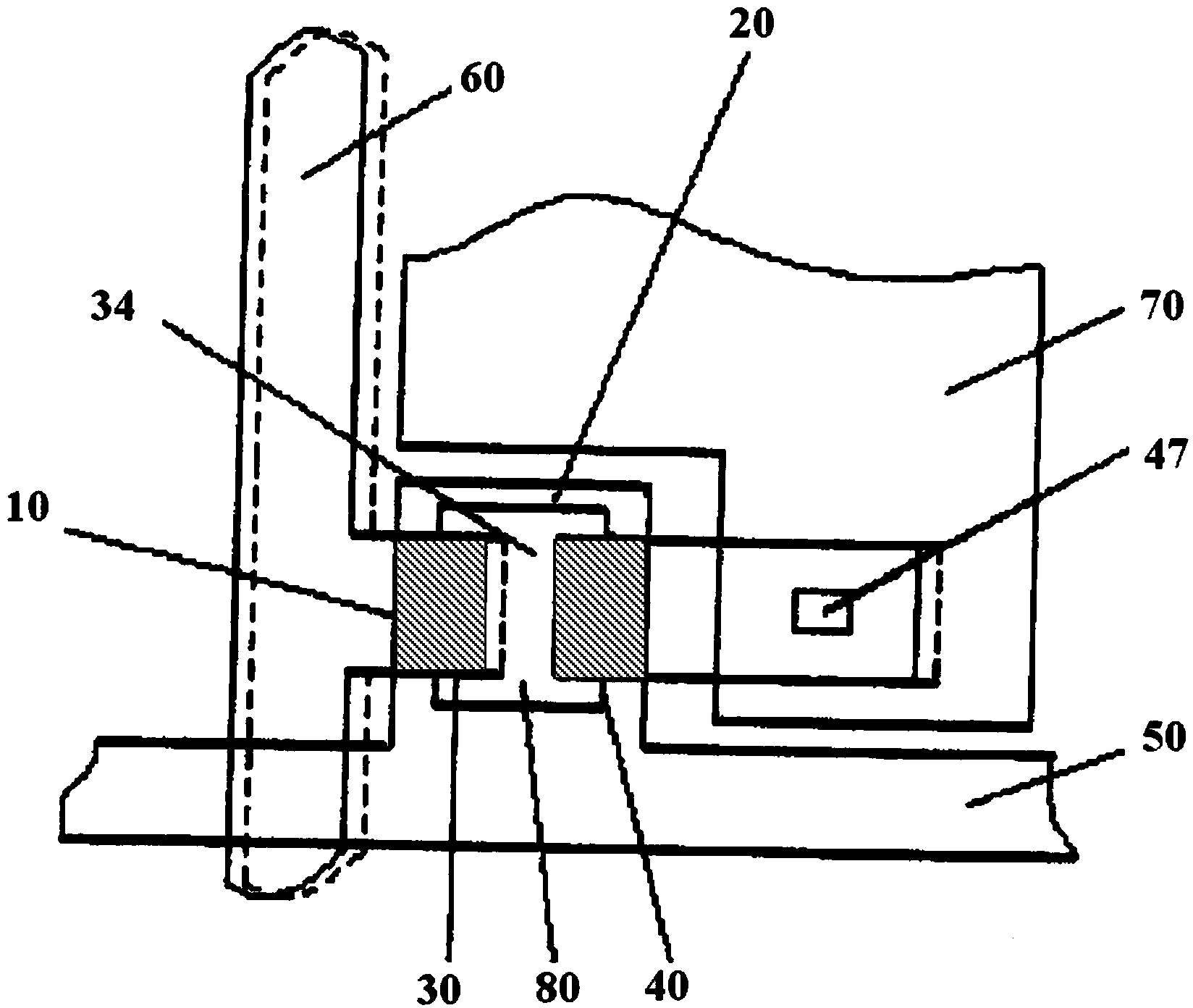
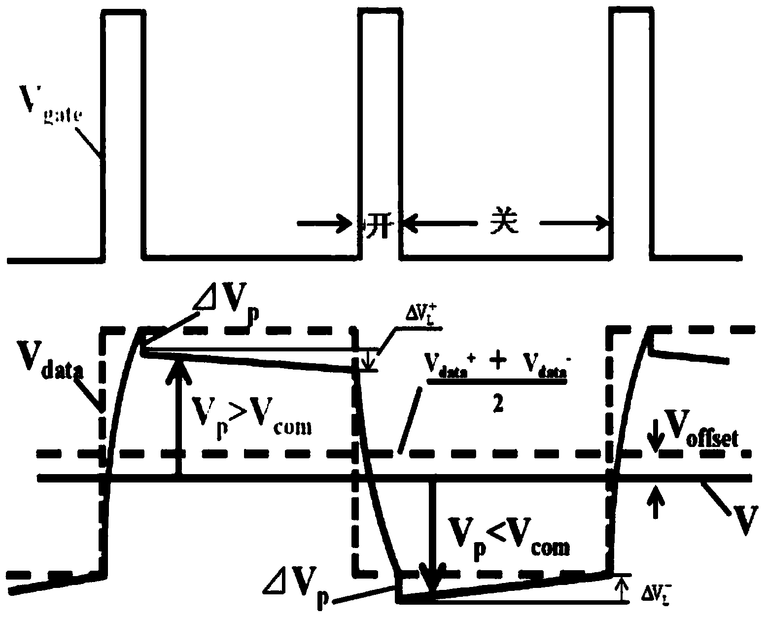
Due to the limitation of objective conditions such as manufacturing process, there will be a certain distribution of the accuracy of the array substrate in the array substrate, so the C of each pixel unit in the array substrate will be gd has a difference
This difference will cause the △V of each pixel electrode in the panel p The distribution is uneven, which will bring defects such as flickering and afterimage to the screen display of the panel
[0008] In the prior art, although a special compensation structure is designed in the thin film transistor to balance the adverse effects of the change of the parasitic capacitance on the image display, it is necessary to sacrifice the aperture ratio of the pixel unit while setting the compensation structure, which reduces the performance of the liquid crystal display. panel display brightness

Method used


Image

  • Thin film transistor and array substrate
  • Thin film transistor and array substrate
  • Thin film transistor and array substrate

Examples


Embodiment Construction

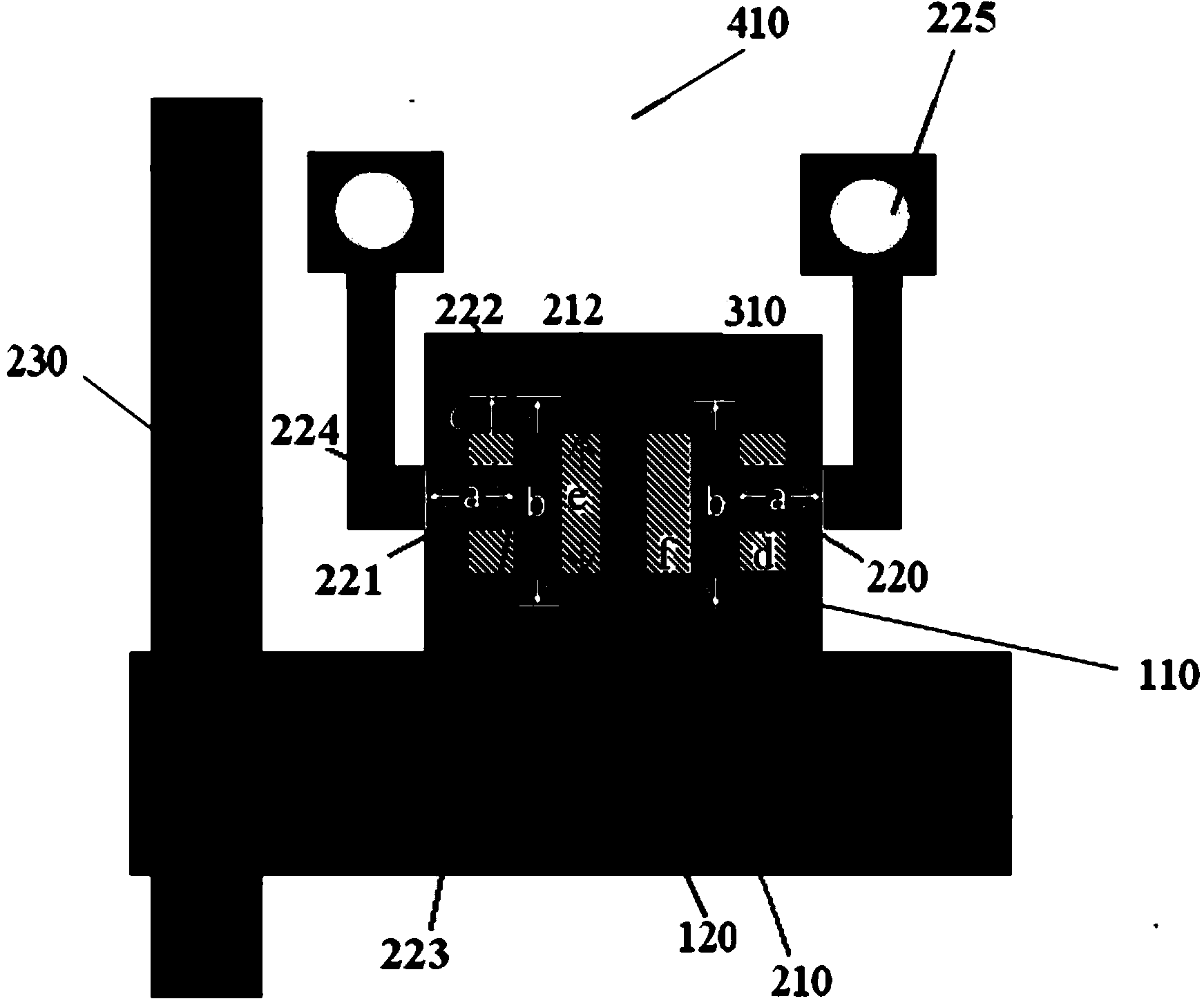
[0048] In order to avoid the uneven distribution of the gate-drain parasitic capacitance of the thin film transistors in the array substrate due to the pair offset between the gate metal and the source and drain metals, the present invention proposes a new method that can realize gate - Thin film transistor structure with drain parasitic capacitance compensation. The technical solution and the technical effects it can achieve will be further described in detail below with reference to the accompanying drawings and specific embodiments. It should be noted that the directional terms mentioned below, such as up, down, left, right, inside, outside, etc., are only for reference to the directions shown in the drawings, and are not used to limit the present invention.

[0049] like image 3 Shown is a schematic plan view of a thin film transistor used in an embodiment of the present invention. Similar to the traditional thin film transistor, the thin film transistor proposed by the...


PUM


Abstract

The invention relates to a thin film transistor and an array substrate. The array substrate comprises multiple pixel units which are arranged in an array mode, wherein each pixel unit corresponds to a scanning line and a data line and comprises a thin film transistor and a pixel electrode, and each thin film transistor comprises a grid electrode electrically connected with the corresponding scanning line, an island area arranged above the grid electrode, a source electrode arranged above the island area and electrically connected with the corresponding data line, and multiple drain electrodes used for outputting the same signal to the pixel electrode and arranged on the two sides of the source electrode in the mode that the drain electrodes are spaced from the source electrode. When relative deviation occurs between the grid electrode and the source electrode and between the grid electrode and the drain electrodes, the sum of the areas of overlapping regions between the grid electrode and the multiple drain electrodes is kept unchanged, the sum of the areas of overlapping regions between the island area and the multiple drain electrodes is also kept unchanged, and thus the grid electrode-drain electrode stray capacitance of the thin film transistor can be kept unchanged. Internal capacitance of the array substrate provided with the thin film transistors is evenly distributed, and thus the image display quality of a liquid crystal display panel can be improved.

Description

technical field [0001] The invention relates to liquid crystal display technology, in particular to a thin film transistor capable of compensating parasitic capacitance and an array substrate. Background technique [0002] As the current mainstream display technology, thin film transistor liquid crystal display panel (TFT-LCD) has the advantages of high brightness, wide viewing angle, full color, high resolution, fast response and low power consumption. Usually, such a liquid crystal display panel is mainly composed of an array substrate, a color filter substrate, and a liquid crystal material sandwiched between the array substrate and the color filter substrate. Wherein, a plurality of pixel units (pixels) are arranged in an array form on the array substrate. Each pixel unit is an area defined by two scan lines and two data lines, and the area includes at least one thin film transistor and a pixel electrode. The thin film transistor, as a switching element that controls t...

Claims


Application Information

Patent Timeline
IPC IPC(8): H01L29/786H01L29/06H01L29/417H01L27/02
CPCH01L27/1214H01L29/78618H01L29/78624
Inventor 徐向阳
Owner TCL CHINA STAR OPTOELECTRONICS TECH CO LTD
Learn More