Linear moving device

A direct-acting device and sliding plate technology, which is applied to transmission devices, electromechanical devices, and electric components, etc., can solve the problems of large motor load, large sliding resistance, and complex structure of the driving device, so as to prevent large-scale and dust intrusion. Effect

Active Publication Date: 2014-07-02
KURODA PRECISION INDS
View PDF9 Cites 7 Cited by
  • Summary
  • Abstract
  • Description
  • Claims
  • Application Information

AI Technical Summary

Problems solved by technology

[0018] In addition, in order to reduce the friction caused by the tension of the belt-shaped sealing ring, it is necessary to use rollers or low-friction materials between the belt-shaped sealing ring and the table, and the structure is relatively complicated.
[0019] In addition, there is a problem that the sliding resistance of the device itself is large due to the tension or friction of the belt-shaped seal ring, and the load on the motor of the driving device is large.

Method used


Image

  • Linear moving device
  • Linear moving device
  • Linear moving device

Examples


no. 1 approach )

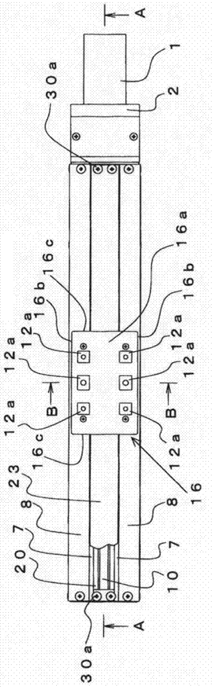
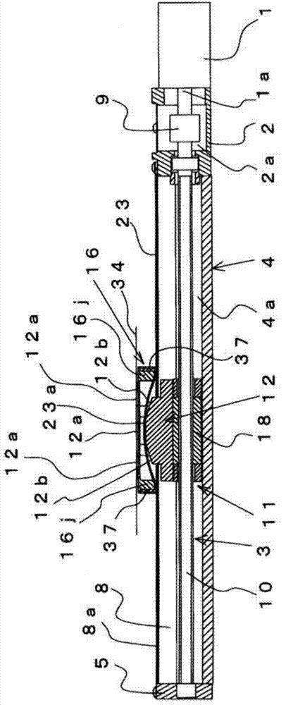
[0096] Figure 1 to Figure 13 A direct motion (direct motion) device according to the first embodiment of the present invention is shown.

[0097] In the figure, 1 is a motor, 2 is a bracket which connects the ball screw 3 accommodated in the case 4, and the motor 1.

[0098] bracket 2 as figure 1 , figure 2 As shown, one end is connected to the motor 1 via a screw. In addition, the bracket 2 is provided with a hollow portion 2 a along the axial direction of the housing 4 , and a coupling portion 9 such as a coupling is provided in the hollow portion 2 a. The motor shaft 1 a is connected to the screw shaft 10 of the ball screw 3 at the connecting portion 9 .

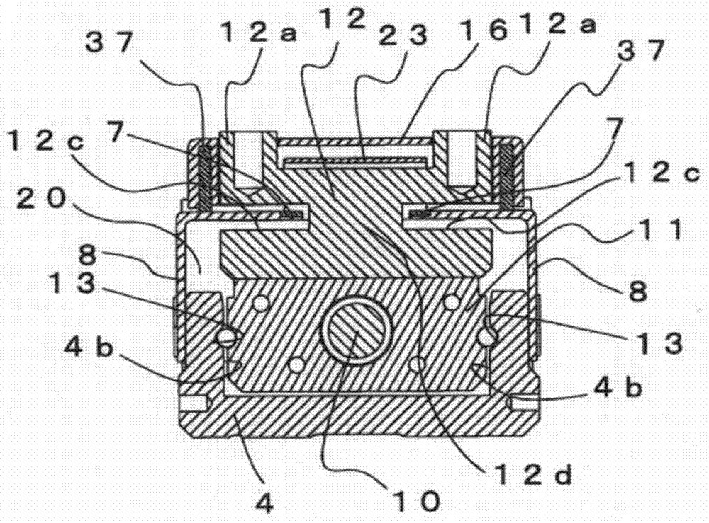
[0099] Housing 4 as figure 2 , image 3 As shown, an opening 20 is formed at the top in the axial direction along the moving direction of the slider 11 , that is, in the axial direction, and both ends in the axial direction are open. The recess 4a formed by the opening 20 is formed with a guide groove 13 for fre...

no. 2 approach )

[0165] Figure 15 to Figure 18 A linear motion device according to a second embodiment of the present invention is shown.

[0166] The linear motion device may require the length of the table 12 to be increased in order to increase the bearing capacity of the table 12 .

[0167] However, in the linear motion device related to the first embodiment, if it is desired to increase the bearing capacity of the workbench 12, the workbench 12 such as image 3 As shown, since the recesses 12c into which the side covers 8 enter are formed on both sides in the longitudinal direction, the table 12 is formed with narrowed portions 12d, and the strength of the table 12 may decrease.

[0168] Therefore, in this embodiment, the bearing capacity of the workbench 12 can be increased by lengthening the length of the workbench 12 and increasing the cross-sectional area of ​​the narrowed portion 12d.

[0169] And, if the bending portion 23a of the belt-shaped sealing ring 23 passing through the u...


PUM


Abstract

The objective of this invention is to prevent dust from entering a case. The solution of this invention is that: a tape-shaped sealing stripe is provided and having a length capable of crossing on a top of a platform for sealing an opening, an sealing stripe guide part is in contact with the tape-shaped sealing stripe while the tape-shaped sealing stripe crosses on the top of the platform so as to bend the tape-shaped sealing stripe, thus an elastic thrust is generated for fixing the portion of the tape-shaped sealing stripe, which does not cross the top of the platform, to an adhesion component, and a slide sheet seals gaps formed between a platform cover and the top of a lateral cover and the tape-shaped sealing stripe while the tape-shaped sealing stripe crosses the top of the platform.

Description

[0001] The present invention is a divisional application of the Chinese patent application number 201010206003.2 and the title of the invention "direct motion device" submitted by the applicant on June 17, 2010. technical field [0002] The present invention relates to, for example, a linear motion device for linearly moving a slider through a ball screw or a hydraulic cylinder, and particularly relates to an anti-friction mechanism between a workbench connected to the slider and a housing housing the slider that operates the workbench. Improvement of the dust device. Background technique [0003] Conventionally, such a linear motion device has provided a strip-shaped sealing ring on the opening of the housing in order to prevent dust from entering the housing. [0004] However, since the table is connected to the slider, it has a structure in which the belt-shaped seal ring spans over the slider. Therefore, dust may intrude into the housing from the gap of the strip-shaped...

Claims


Application Information

Patent Timeline
Patent Type & Authority Applications(China)
IPC IPC(8): H02K7/06F16H25/20F16J15/16F16J15/22
CPCF16H25/20F16H25/2418F16J15/22
Inventor 大野敏明
Owner KURODA PRECISION INDS
Why Eureka
Try Eureka