
A coaxial sleeve type permanent magnet eddy current coupling with fixed end faces

A permanent magnet eddy current, sleeve-type technology, applied in the direction of controlling mechanical energy, electrical components, electromechanical devices, etc., can solve the problems of increasing the force of the prime mover or load shaft supporting bearings, reducing the effective working life, and poor working conditions, etc., to achieve The effect of reducing the workload and simplifying the difficulty of installation

Inactive Publication Date: 2016-04-20
NORTHEASTERN UNIV LIAONING
View PDF6 Cites 0 Cited by
  • Summary
  • Abstract
  • Description
  • Claims
  • Application Information

AI Technical Summary

Problems solved by technology

[0003] However, the existing patented technology of permanent magnet eddy current transmission generally does not pay enough attention to the positioning and connection methods of the permanent magnet rotor and the eddy current ring rotor. The existing coaxial sleeve type permanent magnet eddy current coupling products usually use the following two types One of the ways to realize the installation and positioning of the two rotors: one is to directly set the rotor body on the prime mover or the drive shaft of the load by using the connecting sleeve; the other is to set up special brackets to support the two rotors separately, Connect the shaft of the prime mover and load with the shafts of the two rotors using the coupling parts
These two connection methods have obvious disadvantages: the former connection method applies all the weight and force of the rotor directly on the prime mover or the rotating shaft of the load, especially when the pulley or gear is directly installed. The radial force greatly increases the force of the prime mover or the supporting bearing of the load shaft, resulting in poor working conditions, increased vibration noise, and reduced effective working life; the latter connection method is due to the addition of one or two It is more difficult to ensure the coaxial positioning of the rotating shaft between the prime mover, the load and the bracket, which brings great inconvenience to the installation work, and also brings more excitation sources and uncertain and harmful factors to the system operation.

Method used


Image

  • A coaxial sleeve type permanent magnet eddy current coupling with fixed end faces
  • A coaxial sleeve type permanent magnet eddy current coupling with fixed end faces
  • A coaxial sleeve type permanent magnet eddy current coupling with fixed end faces

Examples


Embodiment 1

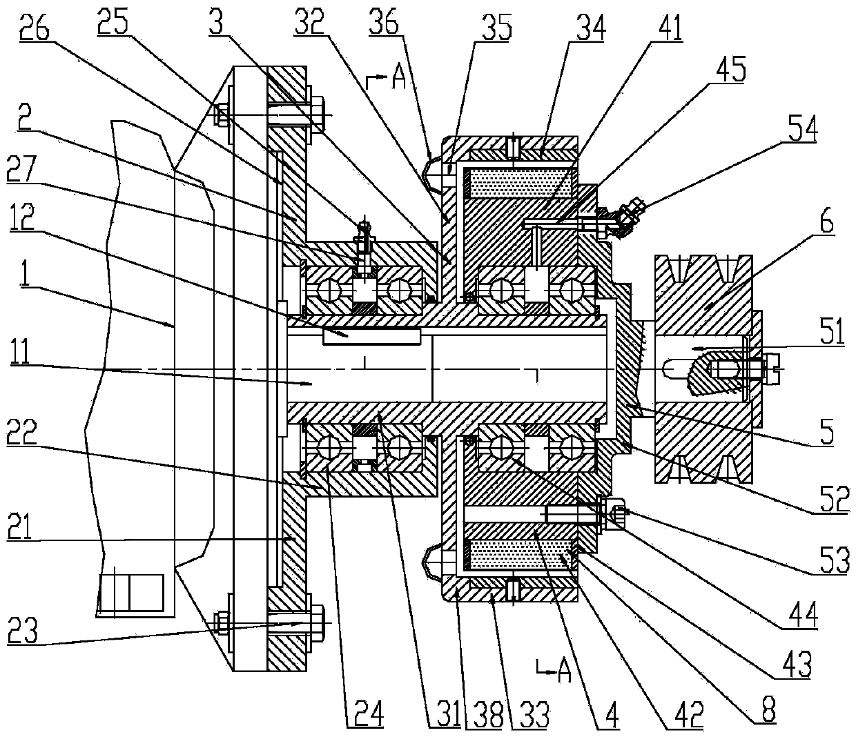
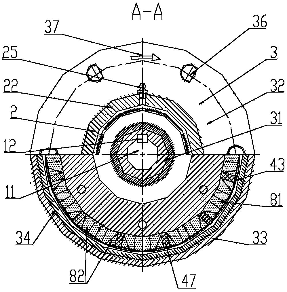
[0023] Such as figure 1 , figure 2As shown in the figure, a coaxial sleeve type permanent magnet eddy current coupling with fixed end face includes a coaxial end face positioning seat 2, a driving rotor 3 and a driven rotor 4; the driving rotor 3 is used as the outer rotor, and the driving rotor body 38 and the eddy current ring 34 fixed on the active rotor body 38; the active rotor body 38 is composed of a hollow shaft 31, an outer liner 33 and a middle support plate 32, and the hollow shaft 31 is a cylindrical structure, which is arranged on the active rotor At the center of the body 38, the middle support plate 32 is a disc-shaped structure, which is coaxially fixed in the middle of the outer wall of the hollow shaft 31; the outer liner 33 is a thin-walled cylindrical structure, made of magnetically conductive material, and fixed on the middle support plate 32 side, the outer liner 33 is coaxially arranged with the hollow shaft 31; the inner side wall of the hollow shaft ...

Embodiment 2

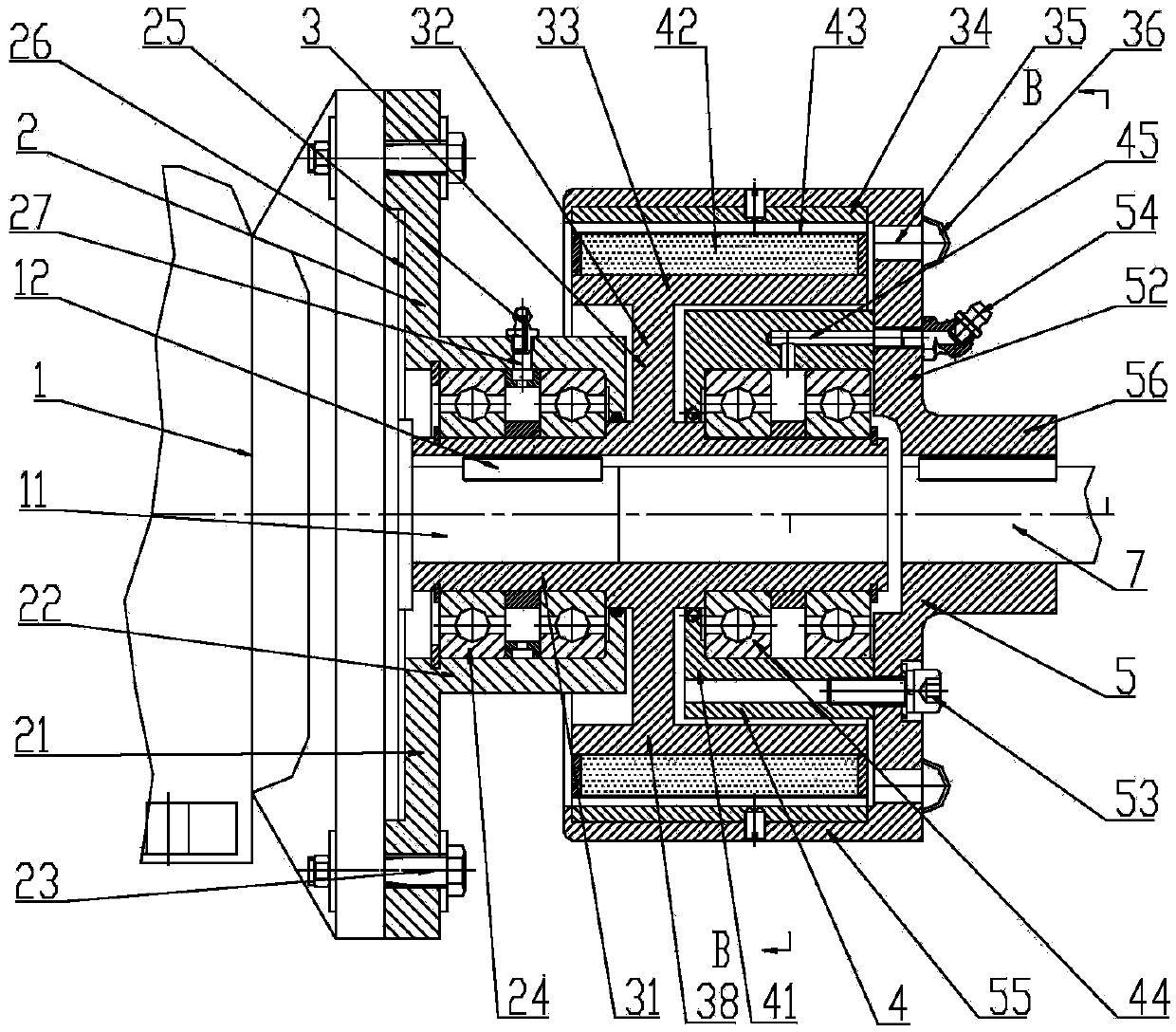
[0031] Such as image 3 , Figure 4 As shown in the figure, a coaxial sleeve type permanent magnet eddy current coupling with fixed end face includes a coaxial end face positioning seat 2, a driving rotor 3 and a driven rotor 4; the driving rotor 3 is used as an inner rotor, and the driving rotor body 38 and the permanent magnet layer 42 arranged on the active rotor body 38; the active rotor body 38 is composed of a hollow shaft 31, an outer liner 33 and a middle support plate 32, and the hollow shaft 31 is a cylindrical structure, which is arranged on the active The center of the rotor body 38; the middle support plate 32 is a disc-shaped structure, coaxially fixed in the middle of the outer wall of the hollow shaft 31; the outer lining 33 is a thin-walled cylindrical structure, made of magnetic material, fixed in the One side of the support plate 32, and the outer liner 33 is coaxially arranged with the hollow shaft 31; a keyway is provided on the inner side wall of the hol...


PUM


Abstract

A coaxial sleeve-type permanent magnet eddy current coupling with fixed end faces, belonging to the technical field of permanent magnet eddy current transmission. The invention can automatically ensure coaxial positioning during installation and operation, greatly simplifying installation difficulty and reducing workload. During operation, the gravity and external force exerted by the permanent magnet eddy current coupling can be directly transferred to the motor stator. Avoid additional external forces on the motor shaft system. The invention includes a coaxially arranged active rotor, a driven rotor and an end positioning seat; the active rotor, as an outer rotor, is composed of an active rotor body and an eddy current ring or permanent magnet layer fixedly arranged on the active rotor body; the active rotor body is composed of a hollow It consists of a core shaft, an outer lining cylinder and a middle support plate. The end positioning seat is set on the hollow shaft. The end positioning seat is composed of an end positioning plate and a bearing seat. The driven rotor serves as the inner rotor and consists of an end cover shaft, a cylinder It consists of a driven rotor body and an eddy current ring or permanent magnet layer fixed on the driven rotor body.

Description

technical field [0001] The invention belongs to the technical field of permanent magnet eddy current transmission, in particular to a coaxial sleeve type permanent magnet eddy current coupling with fixed end faces. Background technique [0002] The basic working principle of permanent magnet eddy current transmission technology is: when the permanent magnet rotor and the eddy current ring rotor make relative rotation motion, the permanent magnets arranged alternately in the direction of magnetic poles on the permanent magnet rotor will generate alternating currents in the eddy current ring made of conductive materials. The magnetic field is changed, and then an alternating eddy current is induced in it, and the eddy current generates an induced magnetic field in the eddy current ring, and the induced magnetic field interacts with the constant magnetic field on the permanent magnet rotor, so that the magnetic field between the two rotors Generate coupling torque, so as to ach...

Claims


Application Information

Patent Timeline
Patent Type & Authority Patents(China)
IPC IPC(8): H02K51/00H02K7/10
Inventor 张世伟边帅赵克中王德喜
Owner NORTHEASTERN UNIV LIAONING
Learn More