Electric appliance fast-assembly heat dissipation device and manufacturing method thereof
A technology of heat dissipation device and quick installation, which is applied in manufacturing tools, structural parts of electrical equipment, cooling/ventilation/heating renovation, etc. Small interior space, firm release elastic fixing effect
- Summary
- Abstract
- Description
- Claims
- Application Information
AI Technical Summary
Problems solved by technology
Method used
Image
Examples
no. 1 example
[0026] The heat dissipation shell of power supply appliances and power controllers is composed of metal profiles or sheet metal stamping, and connectors are required to fix the internal heating components to the radiator to transmit heat.
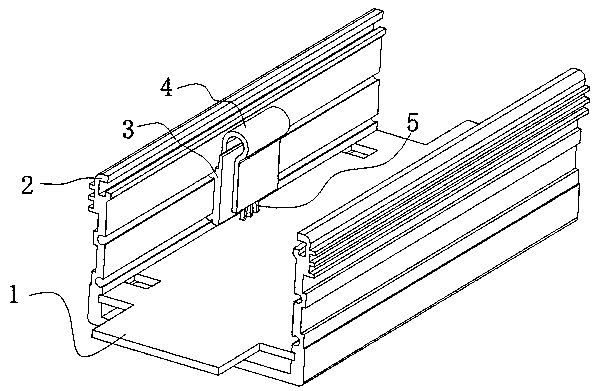
[0027] Depend on image 3 It can be seen from the axonometric drawing that the present invention is composed of a radiator 2, an intermediate cooling block 3 and a heating element 5, the radiator 2 and the intermediate cooling block 3 are cut from extruded metal profiles, and the heating element 5 is welded on the circuit board 1, Clamped in the middle of the middle cooling block 3 , the middle cooling block is closely attached to the side of the radiator 2 .
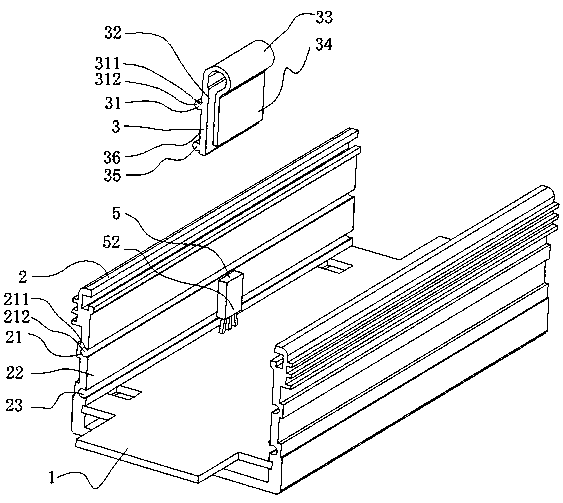
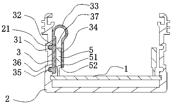
[0028] Depend on figure 1 As can be seen from the assembly schematic diagram, the second side 36 of the middle cooling block 3 is provided with a raised bar 31, the root size 311 of the raised bar 31 is smaller than the middle size 312, and the cross-section is larger on the outside...
no. 2 example
[0033] Figure 5 It is the isometric view of this embodiment. It can be seen from the figure that there is an elastic pressing piece 4 on the upper part of the middle cooling block 3 , the middle cooling block 3 is clamped on the side of the cooling fin 2 , and the heating element 5 is fixed on the circuit board 1 .
[0034] Depend on Figure 4 , Image 6 It can be seen that there is a stepped groove 38 on the middle cooling block 3, and an independent U-shaped elastic pressing piece 4 is clamped in the stepped groove 38, and one end 45 of the U-shaped elastic pressing piece 4 is stuck in the stepped groove 38 at the top of the middle cooling block. , the other end of the elastic pressing piece 4 extends into a clamping portion 44, the middle part of the elastic pressing piece has an arc segment 41, a narrow cavity 42 is formed between the side 43 of the clamping portion and the first side 32 of the middle cooling block, The heating element 5 is clamped in this cavity 42 . ...
Embodiment 2
[0035] Embodiment 2 adds an elastic pressing piece 4, which is combined with the middle cooling block 3 to complete the clamping function. The elastic pressing piece 4 is made of thinner metal elastic material, which further reduces the occupied space. Due to the use of special metal shrapnel , the elasticity is better, and the deformation size of the clamping cavity 42 is also increased, so that heating elements of different thicknesses can be clamped, and the application range is wider.
[0036] Manufacturing method embodiment, see Figure 7, the manufacturing method includes the following steps: first execute step S1, press the heating element against the side of the middle heat dissipation block; then execute step S2, snap the heating element into the cavity formed by the middle heat dissipation block, and utilize the elastic deformation of the cavity, Clamp the heating element so that the heat can be transferred to the middle cooling block; execute step S3, push the circu...
PUM
 Abstract
Description
Claims
Application Information
 - R&D
- Intellectual Property
- Life Sciences
- Materials
- Tech Scout
- Unparalleled Data Quality
- Higher Quality Content
- 60% Fewer Hallucinations
Browse by: Latest US Patents, China's latest patents, Technical Efficacy Thesaurus, Application Domain, Technology Topic, Popular Technical Reports.
© 2025 PatSnap. All rights reserved.Legal|Privacy policy|Modern Slavery Act Transparency Statement|Sitemap|About US| Contact US: help@patsnap.com


