Wireless low-jitter transmission method for high-precision digital asynchronous pulse

A low-jitter, high-precision technology, applied in pulse processing, pulse technology, electrical components, etc., can solve the problems of time-consuming and labor-intensive system debugging, limited accuracy improvement, and reduced edge jitter, etc., to achieve easy debugging, good consistency, and low design effect of difficulty

Active Publication Date: 2014-07-02
NO 54 INST OF CHINA ELECTRONICS SCI & TECH GRP
View PDF3 Cites 7 Cited by
  • Summary
  • Abstract
  • Description
  • Claims
  • Application Information

AI Technical Summary

Problems solved by technology

Under the current technical conditions, this is difficult to achieve
In the existing synchronous low-jitter transmission method, the low-jitter transmission of pulses is at the expense of system bandwidth; at the sending end, only the synchronization of pulse edges and clock edges can be handled, which limits its application in radar pulse transmission; and The analog phase-locked loop circuit is used at the receiving end to reduce edge jitter, and the system debugging is time-consuming and laborious, and the improvement of accuracy is limited

Method used


Image

  • Wireless low-jitter transmission method for high-precision digital asynchronous pulse
  • Wireless low-jitter transmission method for high-precision digital asynchronous pulse

Examples


Embodiment Construction

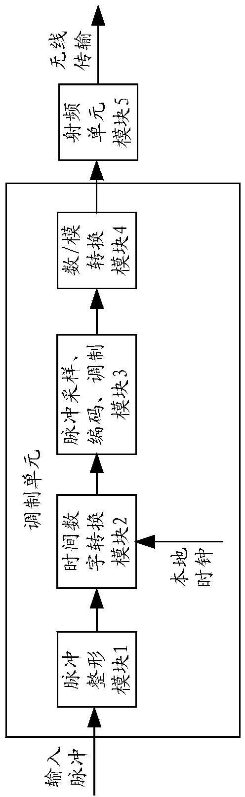
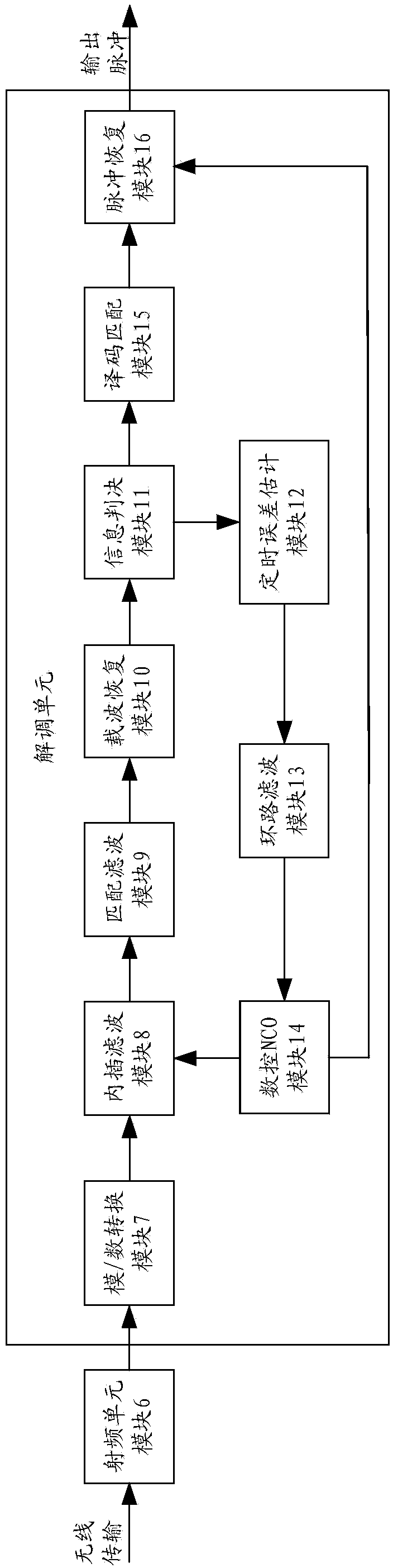
[0031] refer to Figure 1 to Figure 2 . figure 1 It is a block diagram of the electrical principle of an embodiment of the internal processing from the wired side signal to the wireless side of the present invention, which includes a pulse shaping module 1, a time-to-digital conversion module 2, a pulse sampling, encoding, and modulation module 3, a digital / analog conversion module 4, and a radio frequency unit module 5; wherein the pulse shaping module 1, the time-to-digital conversion module 2, the pulse sampling, coding, modulation module 3, and the digital / analog conversion module 4 form a modulation unit. The pulse shaping module 1 completes the pulse deformation correction on the wired line transmission; the time-to-digital conversion module 2 converts the time difference between the pulse-shaping asynchronous pulse signal and the rising edge or falling edge of the local clock into a digital signal; pulse sampling, encoding, The modulation module 3 performs pulse sampli...


PUM


Abstract

The invention relates to a wireless low-jitter transmission method for a high-precision digital asynchronous pulse in the field of pulse wireless transmission and communication, and the wireless low-jitter transmission method is particularly suitable for wireless low-jitter transmission of a radar pulse. Pulse shaping is carried out on a transmitting terminal, a time-digital conversion module is used for converting the time difference between an asynchronous pulse signal obtained after pulse shaping and a rising edge or a falling edge of a local clock into a digital signal, and the steps of digital sampling, encoding, modulation and the like are conducted on the digital signal; on a receiving terminal, a timing error estimation module, a loop smoothing module, an NCO module, an interpolation and filtering module and the like are used for improving the precision of the local clock, output pulse phase position errors are reduced on the premise that the bandwidth is not sacrificed, and finally a high-precision low-jitter pulse signal is output. According to the wireless low-jitter transmission method, a full-digital processing method is adopted, and the high-precision asynchronous low-jitter pulse transmission effect can be realized without local clock synchronization. Main circuit components are obtained through FPGAs or ASICs, so that the design difficulty and the modulation difficulty are low.

Description

technical field [0001] The invention relates to a wireless low-jitter transmission method of high-precision digital asynchronous pulses in the field of pulse wireless transmission communications, and is particularly suitable for wireless low-jitter transmission of radar pulses. Background technique [0002] The commonly used pulse digital sampling wireless transmission method can accurately determine the presence or absence of a pulse signal at the receiving end, but the rising edge and falling edge jitter of the received pulse signal is relatively large. To reduce edge jitter, it is necessary to increase the sampling clock frequency, thereby increasing the sampling rate of the pulse. If the requirement for edge jitter is as low as nanoseconds, the required clock frequency is as high as 1GHz or even higher. Under current technical conditions, this is difficult to achieve. In the existing synchronous low-jitter transmission method, the low-jitter transmission of pulses is a...

Claims


Application Information

Patent Timeline
Patent Type & Authority Applications(China)
IPC IPC(8): H03K5/135
Inventor 毛晶晶王栋良王伟陈小溪
Owner NO 54 INST OF CHINA ELECTRONICS SCI & TECH GRP
Why Eureka
Try Eureka