Vertical lifting hovercar

A flying car, vertical lift technology, applied in the field of flying cars, can solve the problems of fuel consumption, life, safety, user inconvenience, etc., and achieve the effect of saving horizontal tail, improving safety and flight stability

Inactive Publication Date: 2014-07-09
张廷林
View PDF5 Cites 4 Cited by
  • Summary
  • Abstract
  • Description
  • Claims
  • Application Information

AI Technical Summary

Problems solved by technology

The deficiencies of the first two types are that both need to take off and land on the runway; , all need to be completed with the help of a specific site, which brings great inconvenience to users
The disadvantage of the third type is that th

Method used


Image

  • Vertical lifting hovercar
  • Vertical lifting hovercar
  • Vertical lifting hovercar

Examples


Example Embodiment

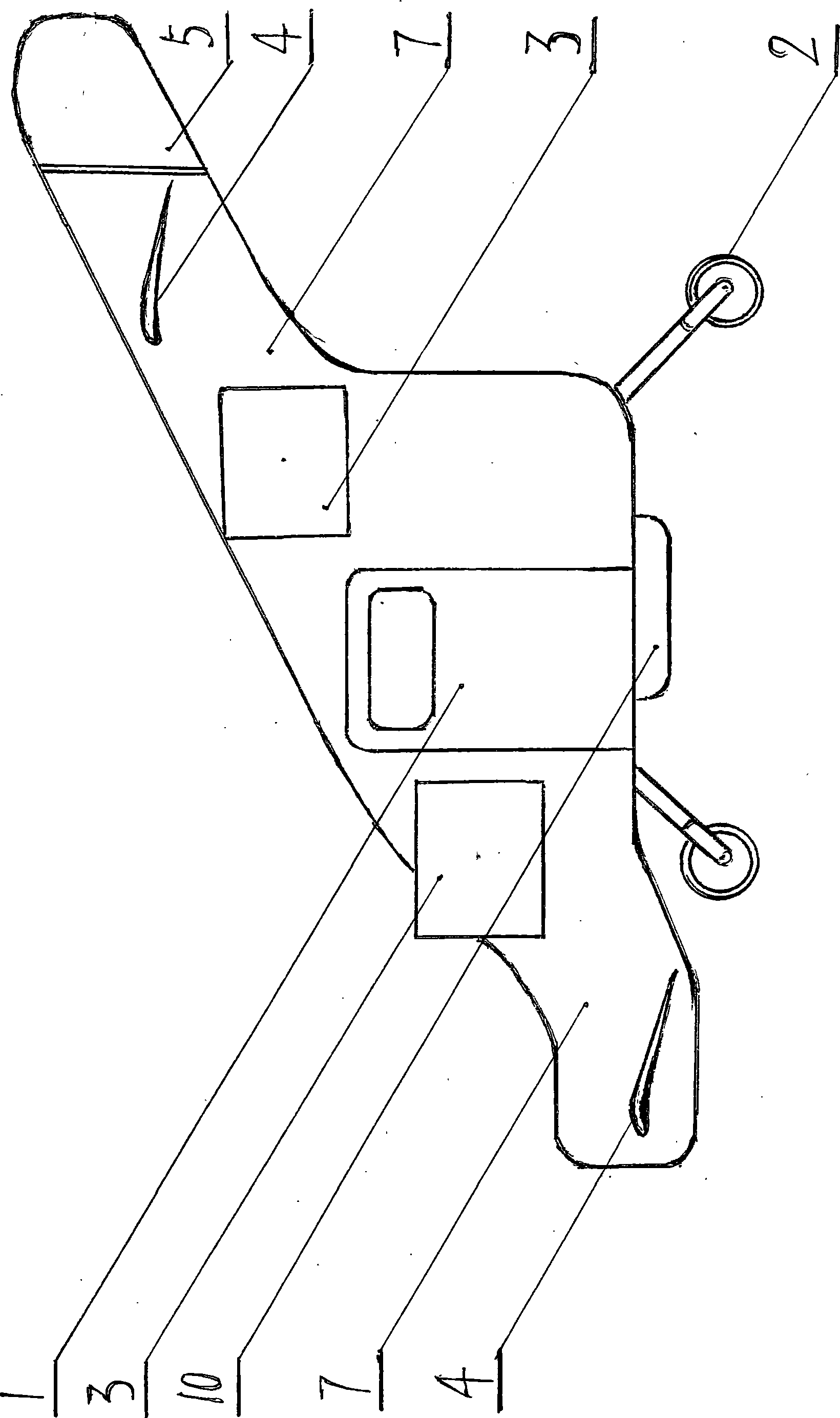
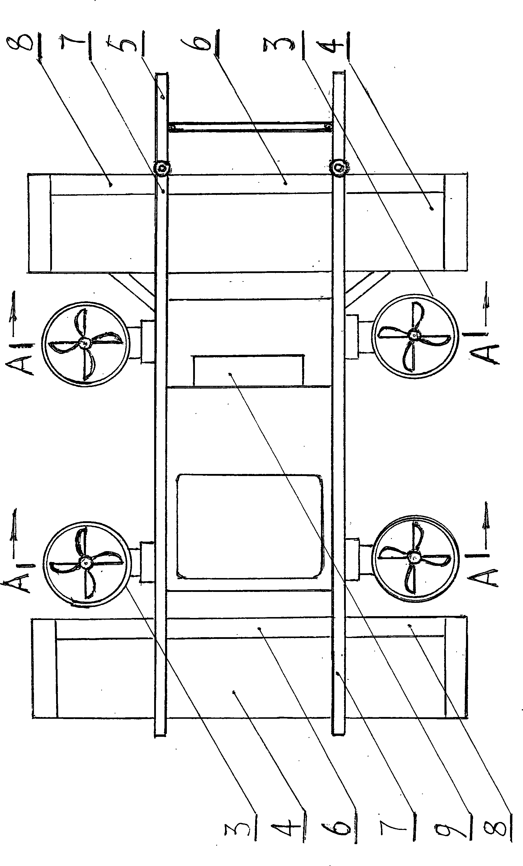
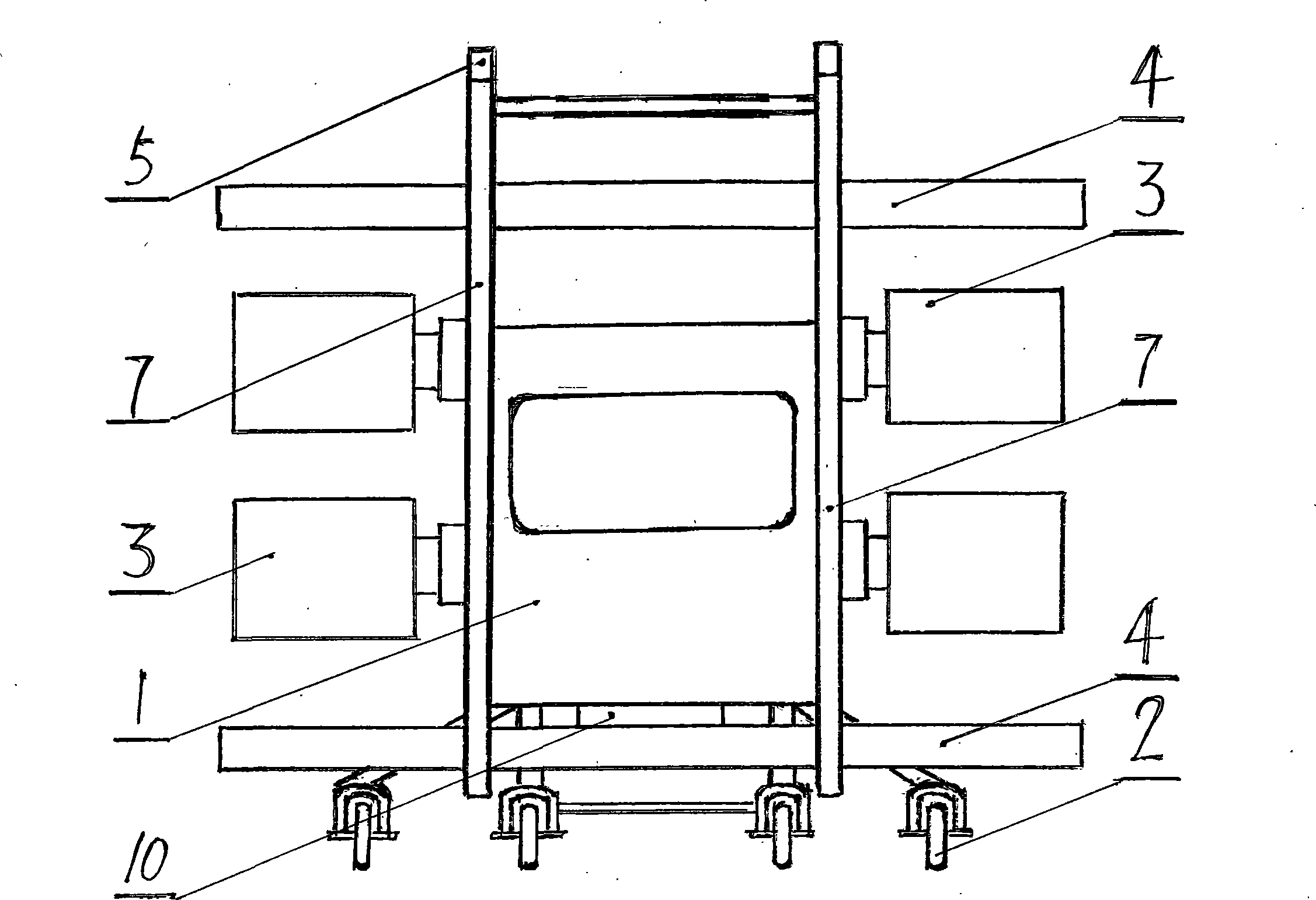
[0014] The flying car of the present invention is equipped with two front and rear engine assemblies, and respectively provides power for the front and rear ducted fans. For the power transmission process, see Figure 4 . The power of the engine assembly 11 is transmitted to the ducted fan blade 15 through the transmission shaft 12 and the bevel gear set 13, which provides power for the flying car to drive on the road or fly in the air. Because of the two ducted fan bevel gear sets 13 on the left and right The installation direction is opposite, and the rotation direction of the fan blades is also opposite, which can make the rotation torque generated by each pair cancel each other and maintain the overall balance of the flying car. The inlet and outlet of the two pairs of ducted fans 3 can be tilted within a range of 180 degrees from horizontal to vertical to horizontal. Refer to the tilting operation process Figure 5 (Combined Figure 4 ), the operating rod 18 is pushed forwa...


PUM


Abstract

The invention discloses vertical lifting hovercar. The vertical lifting hovercar comprises a hovercar body with two irregular vertical plates as the principle portion, wheels, stationary wings, ducted fans and a rudder, wherein the stationary wings, the ducted fans and the rudder are sequentially arranged from the front lower portion to the last rear portion of the hovercar body and respectively fixed on the vertical plates on two sides of the hovercar body. One engine is respectively installed at the front and rear portions of a base plate of the hovercar body and respectively connected with two pairs of ducted fans. When the vertical lifting hovercar runs on a highway, air inlets and outlets of the ducted fans are in a horizontal state, the hovercar runs ahead by utilizing reacting force of the ducted fans push air, and steering and braking are achieved by using a steering wheel and a brake pump to control the wheels. When the vertical lifting hovercar flies in the air, the air inlets and outlets of the ducted fans are in a vertical state, and downward push force produced in working enables the hovercar to achieve vertical lifting and suspension. When the ducted fans obliquely and forward rotate, the hovercar produces horizontal speed, the stationary wings produces lift force, and the ducted fans gradually and mainly provide pushing force for the hovercar. The flying hovercar is controlled by ailerons and flaps of the rudder during steering and lifting.

Description

technical field [0001] The invention relates to a flying car, more specifically, it relates to a vertical lift flying car. Background technique [0002] At present, there are three main types of flying cars on the market. The first is a fixed-wing flying car with foldable wings; the second is a rotor flying car with foldable wings; In automobiles, the horizontal and vertical empennages mainly play a role in controlling flight stability. The deficiencies of the first two types are that both need to take off and land on the runway; , all need to be completed with the help of a specific site, which brings great inconvenience to users. The disadvantage of the third type is that the lift of the flying car is mainly provided by ducted fans, whether it is landing, lifting or level flight, and the engine will be in a high-power working state for a long time, which is not good for fuel consumption, lifespan or safety. Contents of the invention [0003] The content of the present...

Claims


Application Information

Patent Timeline
IPC IPC(8): B60F5/02
Inventor 张廷林
Owner 张廷林
Why Eureka
Try Eureka