
Pedal device

一种踏板、踏板架的技术,应用在机械控制装置、脚动启动装置、制动作用启动装置等方向,能够解决结构繁琐、教示等问题

Active Publication Date: 2016-07-06
F TECH INC
View PDF6 Cites 0 Cited by
  • Summary
  • Abstract
  • Description
  • Claims
  • Application Information

AI Technical Summary

Problems solved by technology

[0004] However, according to the research of the present inventors, in Japanese Patent Laid-Open No. 2008-90381, the control lever 21 is supported by the support shaft 19 provided separately from the pivot 13 of the operation pedal 10, and is held by the support piece 26 and the rivet 27, Furthermore, for the pivot 13 of the operation pedal 10, it is also necessary to provide a breakable partition wall 24, so its structure tends to be cumbersome.
[0005] Furthermore, according to the research of the present inventors, in Japanese Patent Application Laid-Open No. 2008-90381, when the operation pedal 10 is in the retreating posture, as long as the control lever 21 can be moved so that it does not interfere with the vehicle body side unnecessarily, The deformation of the vehicle body can be carried out smoothly, so it is more preferable. However, Japanese Patent Application Laid-Open No. 2008-90381 does not teach such a structure.

Method used


Image

  • Pedal device
  • Pedal device
  • Pedal device

Examples


Embodiment Construction

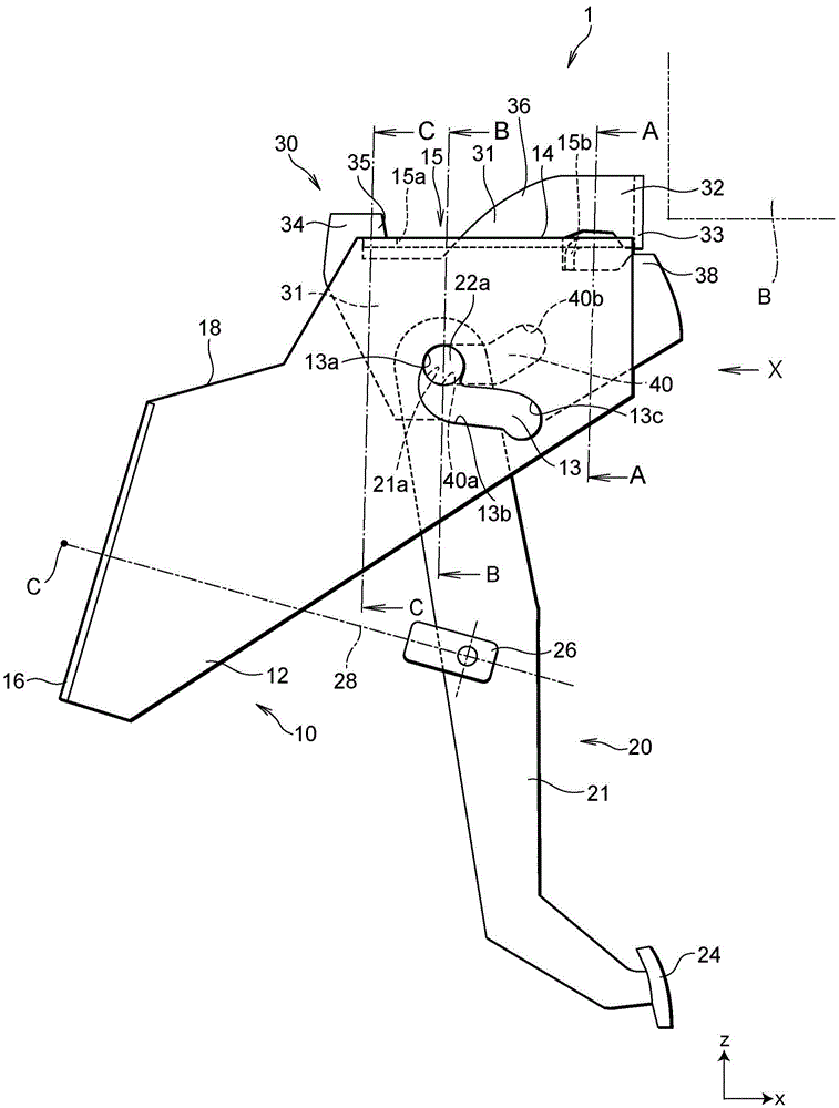
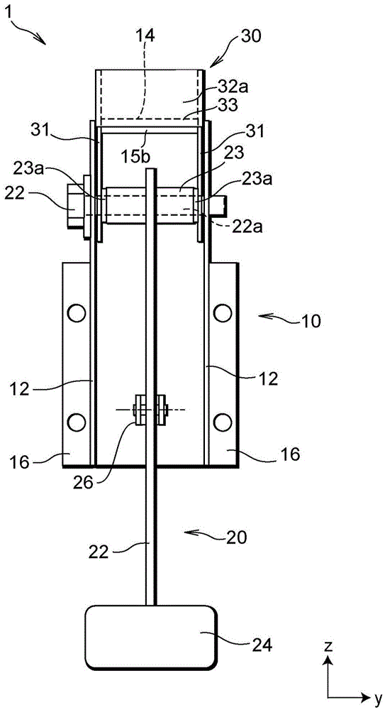
[0041] Hereinafter, the pedal device in the embodiment of the present invention will be described in detail with reference to the drawings as appropriate. In addition, in the drawing, the x-axis, y-axis, and z-axis form a three-axis orthogonal coordinate system. Also, for convenience of description, sometimes the positive direction of the x-axis corresponds to the rear direction, the negative direction of the x-axis corresponds to the front direction, the positive direction of the z-axis corresponds to the upward direction, and the negative direction of the z-axis corresponds to in the down direction. In addition, in figure 1 , for fasteners such as fastening bolts, only the shaft portion is shown for convenience, and in figure 2 and Figure 4 In , illustrations of mating nuts for fastening fasteners such as bolts are omitted for convenience.

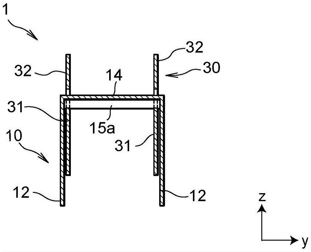
[0042] First, refer to Figure 1 to Figure 5 The structure of the pedal device in this embodiment will be described in detail. ...


PUM


Abstract

The present invention provides a pedal device capable of reliably retracting a pedal arm from a passenger side such as a driver and allowing a retainer, which is a control member for realizing a retracted posture of the pedal arm, to move from the side of a passenger such as a driver during a frontal collision of a vehicle. The side of the vehicle body retreats, wherein the first guide hole (13) provided on the pedal frame (10) assembled on the vehicle body has a start hole (13a), a terminal hole (13c), and a connection start hole (13a) and The connection hole (13b) between the terminal holes (13c) is set in the second guide hole ( 40) It has a first hole (40a) and a second hole (40b) connected to each other.

Description

technical field [0001] The present invention relates to a pedal device, and particularly relates to a pedal device which is mounted on a vehicle such as an automobile and freely controls the posture of a pedal arm when the vehicle collides or the like. Background technique [0002] In recent years, in a pedal device such as a brake pedal device mounted on a vehicle such as a motor vehicle, the following structure has been proposed: in order to prevent the pedal device from moving backward due to the deformation of the vehicle body during a frontal collision of the vehicle and causing the driver and other passengers to Unnecessarily interfere with the feet of the foot, causing a part of the pedal unit to drop or move forward. [0003] Under such circumstances, Japanese Patent Application Laid-Open No. 2008-90381 relates to an operation pedal device for a motor vehicle, and discloses a structure in which when the instrument panel 3 is deformed backward, the pivot shaft 13 is m...

Claims


Application Information

Patent Timeline
Patent Type & Authority Patents(China)
IPC IPC(8): B60T7/06B60R21/09
CPCB60R21/09B60T7/065G05G1/327G05G1/44Y10T74/20528
Inventor 佐藤润小川和夫
Owner F TECH INC
Learn More