Stable yarn frame for spinning

A yarn frame and stable technology, applied in the field of yarn frame, can solve the problems of affecting normal production, potential safety hazards, flying out, etc., achieve the effect of less cost increase, smooth pay-off process, and restrain bobbin bobbing

Inactive Publication Date: 2014-07-09
WUJIANG JIUMEI MICROFIBER WEAVING
View PDF8 Cites 3 Cited by
  • Summary
  • Abstract
  • Description
  • Claims
  • Application Information

AI Technical Summary

Problems solved by technology

However, the existing yarn column is not equipped with any blocking protection device for the convenience of loading and unloading of the yarn bobbin. Therefore, when the yarn bobbin rotates at high speed, it is easy to fly out of the yarn column, which affects normal production and has potential safety hazards.

Method used


Image

  • Stable yarn frame for spinning
  • Stable yarn frame for spinning
  • Stable yarn frame for spinning

Examples


Embodiment Construction

[0020] The present invention will now be further described in detail in conjunction with the accompanying drawings and embodiments. These drawings are all simplified schematic diagrams, only illustrating the basic structure of the present invention in a schematic manner, so it only shows the composition related to the present invention.

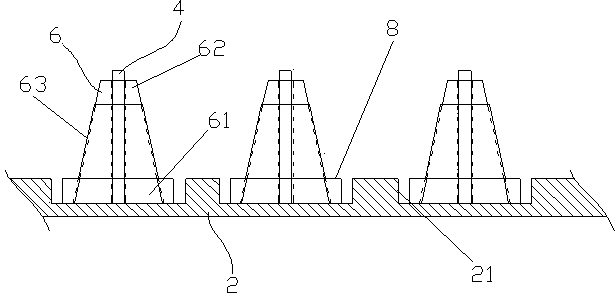
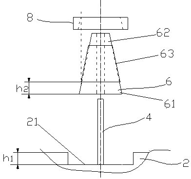
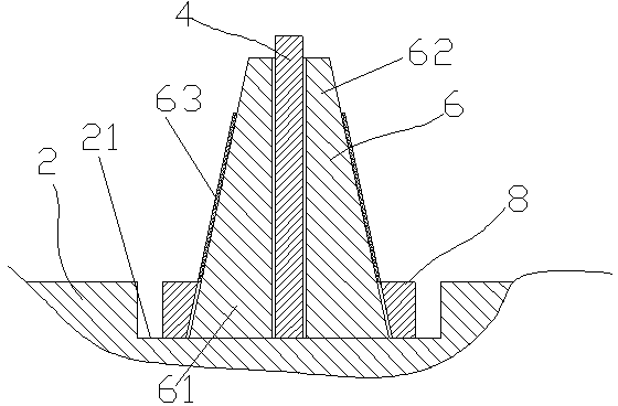
[0021] Such as Figure 1-3 As shown, a stable textile yarn frame includes a plate-shaped base 2 and a plurality of yarn columns 4 arranged vertically on the base 2 in sequence. The yarn columns 4 are used to cover the yarn bobbin 6, and 6 is a conical shape with a large bottom 61 and a small head 62, and the bottom 61 of the bobbin 6 has a certain height of exposed parts. The base 2 is provided with a groove 21 corresponding to the position of each yarn column 4, and the column is arranged in the corresponding groove 21 on the base 2. The groove 21 is cylindrical and has a diameter greater than or equal to the outer diameter of the bottom 61 ...


PUM


Abstract

The invention relates to a stable yarn frame for spinning. The stable yarn frame comprises a tabular base and a plurality of yarn uprights. The sequentially arrayed yarn uprights are vertically arranged on the base and are used for sleeving yarn bobbins. Each yarn bobbin is in the shape of a circular truncated cone with big end down. The bottom of each yarn bobbin has a bare portion with a certain height. The stable yarn frame is characterized in that grooves are formed in positions, corresponding to the yarn uprights, of the base; the uprights are arranged in the corresponding grooves of the base; the diameter of each cylindrical groove is larger than the outer diameter of the bottom of each yarn bobbin. Through the grooves, good limiting and protecting effects to the yarn bobbins jumping in a certain height range during rotating are achieved, and the situation that the yarn bobbins fly from the yarn uprights directly due to high-speed rotation is avoided; the grooves are easy to process, increased cost is low, and influences on normal mounting and demounting of the yarn bobbins are not caused.

Description

technical field [0001] The invention relates to an auxiliary tool for textile equipment, in particular to a yarn frame. Background technique [0002] The yarn frame is a wire storage and pay-off tool commonly used in the textile process in the textile field. The yarn frame usually includes a plate-shaped base and a plurality of yarn columns vertically arranged on the base, and the yarn columns are used for sheathing the yarn bobbins. The yarn bobbin includes a hollow cylindrical body with two ends open and yarns wound on the body. The shape of the main body is a circular truncated shape with a large bottom and a small head. The yarn is wound on the main body, and there are gaps between the two ends of the main body, so the exposed parts are formed on the head and the bottom respectively. Before work, the yarn tube is set on the corresponding yarn column, and the yarn is connected with the textile parts. When weaving, the yarn is pulled to drive the yarn tube to unwind so a...

Claims


Application Information

Patent Timeline
Patent Type & Authority Applications(China)
IPC IPC(8): B65H75/18B65H75/10
Inventor 沈小芳
Owner WUJIANG JIUMEI MICROFIBER WEAVING
Why Eureka
Try Eureka