isochronous transfer structure

A technology of synchronous transmission and transmission wheel, applied in the direction of sending objects, object supply, pile separation, etc., can solve the problems of beating, phase difference, large tension difference, etc.

Active Publication Date: 2016-05-25
SHENZHEN YIHUA COMP +2
View PDF9 Cites 4 Cited by
  • Summary
  • Abstract
  • Description
  • Claims
  • Application Information

AI Technical Summary

Problems solved by technology

However, due to the difference in the processing of the two transmission belts and the elongation of the two transmission belts, the two transmission belts have a phase difference during the transmission process, resulting in a large difference in tension, and even jumping during the transmission process.
In addition, because the conveyor belt and its driving mechanism are set under the conveyor belt, its structure is complicated

Method used


Image

  • isochronous transfer structure
  • isochronous transfer structure
  • isochronous transfer structure

Examples


Embodiment Construction

[0018] The synchronous transmission structure of the present invention will be further described in detail with reference to the accompanying drawings and embodiments.

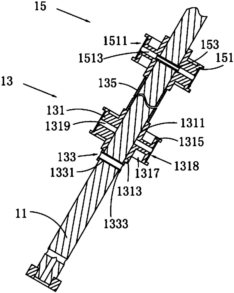
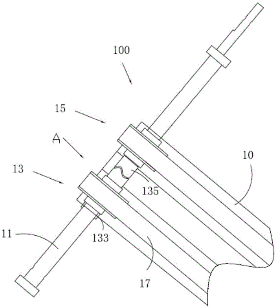
[0019] see figure 1 , the synchronous transmission structure 100 of the present invention includes a delivery seat 10, a driven shaft 11 perpendicular to the delivery seat 10 and arranged at intervals, a first transmission wheel assembly 13 and a second transmission wheel assembly 15 sleeved on the driven shaft 11 at intervals , and two transmission belts 17 respectively arranged on the first transmission wheel assembly 13 and the second transmission wheel assembly 15 . In this embodiment, the synchronous transmission structure 100 is used in an automatic teller machine, and two transmission belts 17 are sandwiched between the transmission seat 10 to transport money.

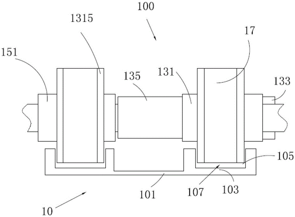
[0020] Please also refer to figure 2 , the conveying seat 10 is strip-shaped, which includes a bottom plate 101 and two conveying parts 103 ...


PUM


Abstract

A synchronous conveying structure comprises a driven shaft, a first transmission wheel, a second transmission wheel, two transmission belts, a conveying seat, a retaining piece and a retaining ring, wherein the first transmission wheel and the second transmission wheel sleeve the driven shaft at interval, the second transmission wheel fixedly sleeves the driven shaft, and the first transmission wheel rotatably sleeves the driven shaft; the conveying seat is provided with at least two conveying units at interval and in parallel; the driven shaft is arranged on the conveying seat at interval; the retaining piece and the retaining ring are mounted on the driven shaft and abuts against both sides of the first transmission wheel to clamp the first driven wheel, so that the axial position of the first transmission wheel relative to the driven shaft can maintain constant; one sides of the transmission belts are accommodated inside the corresponding conveying units to form a conveying passage between the conveying units and the transmission belts. According to the synchronous conveying structure, the two transmission belts can maintain the relative identity in position relatively easily, have small tension difference and avoid fluctuation. Meanwhile, the synchronous conveying structure is simpler in structure.

Description

technical field [0001] The present invention relates to a transmission structure, in particular to a synchronous transmission structure. Background technique [0002] In the prior art, a synchronous transmission structure is usually used to transmit materials, for example, a synchronous transmission structure is used to transmit currency in an automatic teller machine. The synchronous transmission structure includes two conveyor belts, a conveyor belt driving mechanism, a driven shaft, two transmission turbines and two transmission belts. Two conveyor belts are arranged in parallel at intervals, and the driven shaft is arranged at intervals on the two conveyor belts and its axial direction is perpendicular to the conveying direction of the conveyor belts. Two transmission wheels are fixed on the driven shaft at intervals and correspond to the two conveyor belts respectively. The two transmission belts are correspondingly sheathed on the two transmission wheels and are set ...

Claims


Application Information

Patent Timeline
Patent Type & Authority Patents(China)
IPC IPC(8): B65H79/00B65H5/02B65H29/16
Inventor 彭彤陈文
Owner SHENZHEN YIHUA COMP
Why Eureka
Try Eureka