a twisting device

A twisted wire and winch technology, applied in the direction of conductor/cable insulation, electrical components, cable/conductor manufacturing, etc., can solve the problems of twisted wire drum deformation, stress concentration, and inapplicability, so as to reduce the difference in tension and improve the use of The effect of life and tension improvement

Active Publication Date: 2022-05-17
青海鑫邦线缆有限公司
View PDF10 Cites 0 Cited by
  • Summary
  • Abstract
  • Description
  • Claims
  • Application Information

AI Technical Summary

Problems solved by technology

[0008] (1) The synchronous motor of the wire harness machine only drives one end of the stranding drum to rotate, and cannot drive the stranding drum to rotate synchronously everywhere. If the stranding drum grows due to the need to wind multiple wires, it is easy to cause stress to concentrate on the strands. The connection between the wire drum and the drum shaft makes the wire drum deform after long-term use, which affects the service life of the wire harness, so this solution is not suitable for the manufacture of cable bundles with more winding wires;
[0009] (2) When twisting a single wire, if the tension of the single wire changes, it will affect the quality of the twisted cable and reduce the production quality of the wire binding machine

Method used


Image

  • a twisting device
  • a twisting device
  • a twisting device

Examples


Embodiment 1

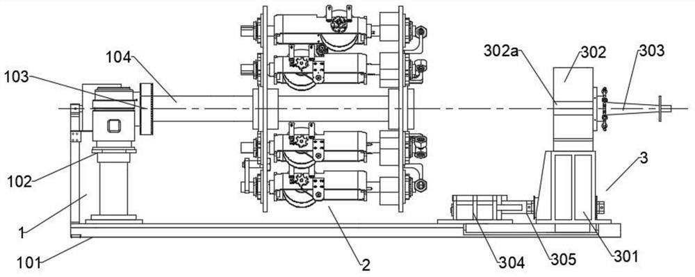
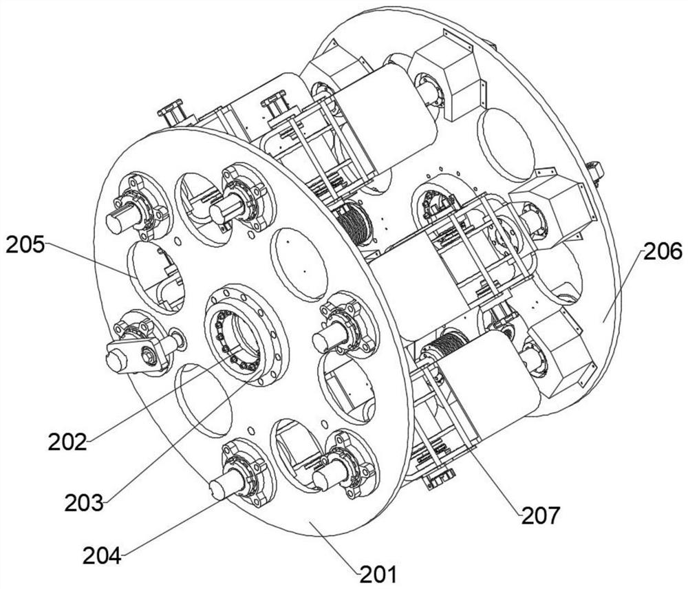
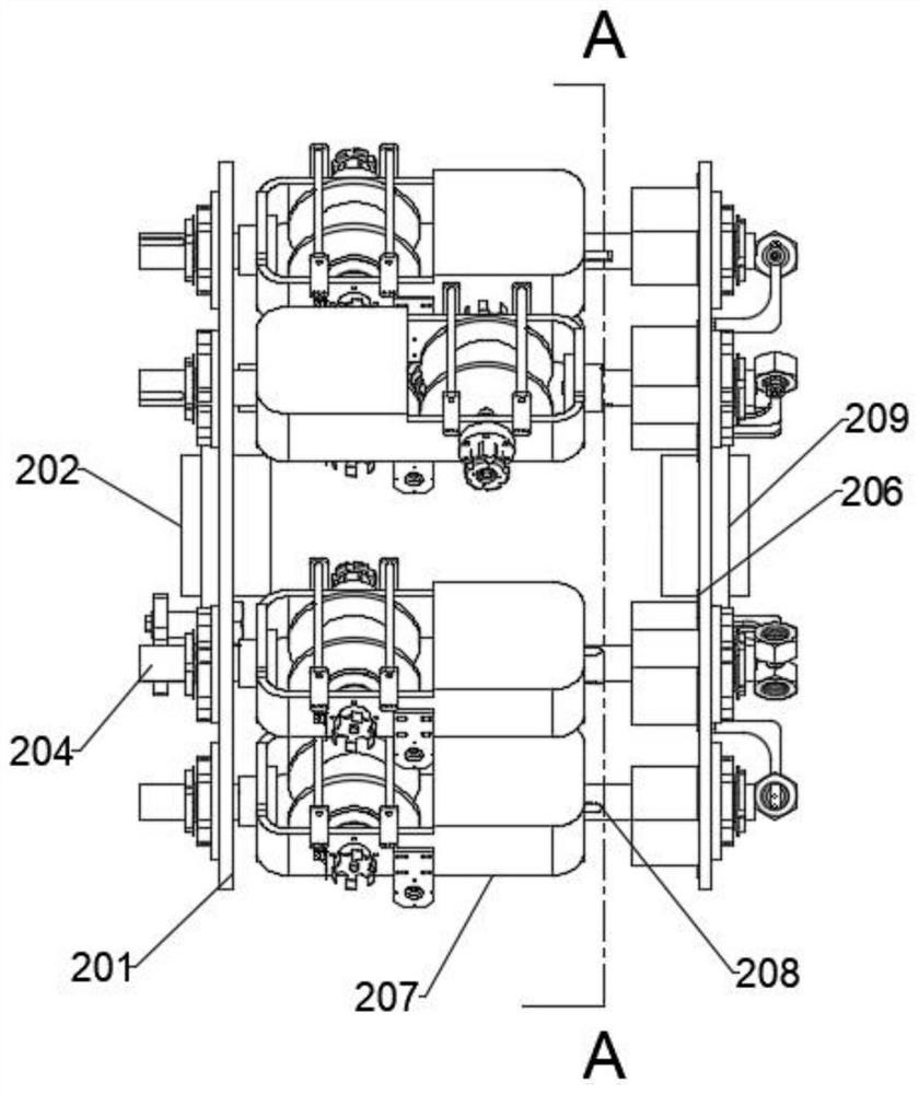
[0050] Such as Figures 1 to 5 As shown, a stranding device includes a driving assembly 1 and a stranding assembly 2. According to the moving direction of the cable, the driving assembly 1 is located at the moving head end of the cable; the driving assembly 1 includes a support plate 101, a main Drive motor 102, main shaft 104, main drive motor 102 is fixedly installed on the front end of support plate 101, main drive motor 102 connects main shaft 104 front ends, and joint is provided with stop plate 103, main shaft 104 end is connected with skeined wire assembly 2; The wire assembly 2 includes a front winch 201, a back-twist unit 207, a rear winch 206 and a twister 3. The middle part of the front winch 201 has a through first connection hole 202, and the middle part of the rear winch 206 has a through second connection hole 209. , the end of the main shaft 104 passes through the first connecting hole 202 and the second connecting hole 209 to connect the front winch 201 and th...

Embodiment 2

[0061] Such as Figures 1 to 7 As shown, a wire twisting device includes a drive assembly 1 and a wire twist assembly 2, and the drive assembly 1 is located at the head end of the cable according to the moving direction of the cable;

[0062] The drive assembly 1 includes a support plate 101, a main drive motor 102, and a main shaft 104. The main drive motor 102 is fixedly mounted on the front end of the support plate 101, the main drive motor 102 is connected to the front end of the main shaft 104, and the end of the main shaft 104 is connected to the twisted wire assembly 2;

[0063] The strand assembly 2 includes a front winch 201, a back-twisting unit 207, a rear winch 206 and a twister 3, the middle part of the front winch 201 has a through first connection hole 202, and the middle part of the rear winch 206 has a through second connection hole 209, the end of the main shaft 104 passes through the first connecting hole 202 and the second connecting hole 209 to connect the...


PUM

PropertyMeasurementUnit
diameteraaaaaaaaaa
thicknessaaaaaaaaaa

Abstract

The invention relates to the technical field of cable processing, in particular to a cable stranding process and a stranding device. The stranding device includes a driving assembly and a stranding assembly. According to the moving direction of the cable, the driving assembly is located at the The moving head end of the cable; the drive assembly includes a support plate, a main drive motor, and a main shaft. It includes a front winch, a back-twist unit, a rear winch and a winch. The middle part of the front winch has a through first connecting hole, and the middle part of the rear winch has a through second connecting hole. The main shaft, the front winch and the rear winch are synchronously driven. The connecting and untwisting unit is arranged between the front winch and the rear winch. The invention is used to solve the problems in the prior art that it is not suitable for the manufacture of cable bundles with many winding wires and that if the tension of a single wire changes during the twisting process, the quality of the twisted cables will be affected.

Description

technical field [0001] The invention relates to the technical field of cables, in particular to a twisting device. Background technique [0002] With the advancement of wire and cable processing technology, the conductors of power cables have begun to develop into a shaped wire stranded structure. The shaped wire stranded conductor has the characteristics of a small outer diameter layer and a smooth surface. And the application of shaped wire stranded conductors in power cables also has the advantages of reducing cable breakdown rate, smaller conductor outer diameter under the same cross-section, reducing the use of insulating materials and sheath materials, and improving conductor compression coefficient (0.98). [0003] Comparing the copper stranded conductor with shaped wire to the round compact conductor, under the same resistance, the plastic variation of copper is small, and the molecular structure distribution in the copper material becomes smaller, so that the resist...

Claims


Application Information

Patent Timeline
Patent Type & Authority Patents(China)
IPC IPC(8): H01B13/00H01B13/02H01B13/14
CPCH01B13/0006H01B13/0016H01B13/02H01B13/0207H01B13/14
Inventor 赵阳孙建营谢夏青赵帅奇冯茹霞
Owner 青海鑫邦线缆有限公司
Why Eureka
Try Eureka