Balancing type adjusting valve

A regulating valve and balanced technology, applied in the field of balanced regulating valves, can solve the problems of large vibration and noise of the valve core, unreasonable structure, laborious opening of the valve, etc., and achieve low vibration and noise of the valve core, reasonable structure, and labor-saving opening of the valve Effect

Inactive Publication Date: 2014-07-09
TIANJIN NUOWEI FLUID CONTROL TECH
View PDF9 Cites 12 Cited by
  • Summary
  • Abstract
  • Description
  • Claims
  • Application Information

AI Technical Summary

Problems solved by technology

[0003] However, the manual control valves in the prior art generally have the problems of unreasonable structure, difficult assembly, labo

Method used


Image

  • Balancing type adjusting valve

Examples


Embodiment Construction

[0016] The present invention will be described in detail below in conjunction with the accompanying drawings.

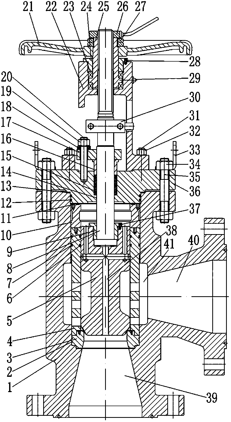
[0017] Such as figure 1 As shown, a balanced regulating valve includes a valve body 1, a valve seat 3, an adjusting sleeve 4, a piston-type regulating valve core 5, a pressure ring 10, a lifting shaft 8, a valve cover 36 and a hand wheel 21, the valve body 1. There is a longitudinal medium inlet 39 and a horizontal medium outlet 40. The medium outlet 40 is located above the medium inlet 39. The medium inlet 39 and the medium outlet 40 are connected by the valve cavity 41 in the valve body 1. The valve seat 3 and the adjustment sleeve 4. The regulating valve core 5 and pressure ring 10 are all set in the valve cavity 41, the valve seat 3 is connected to the bottom of the valve cavity 41, and two first O-rings 2 are arranged between the valve seat 3 and the valve body 1, The adjustment sleeve 4 is connected to the upper end of the valve seat 3, the adjustment valve co...


PUM


Abstract

A balancing type adjusting valve comprises a valve body, a valve seat, an adjusting sleeve, a piston type adjusting valve element, a pressing ring, a lifting shaft, a bonnet and a hand wheel, wherein the bonnet is hermetically connected to the upper end of the valve body; the hand wheel is arranged at the upper end of the lifting shaft; the valve body is provided with a longitudinal medium inlet and a transverse medium outlet; the medium inlet is connected with the medium outlet via a valve cavity in the valve body; the valve seat, the adjusting sleeve, the adjusting valve element and the pressing ring are arranged in the valve cavity; the valve seat is connected to the bottom of the valve cavity; the adjusting sleeve is connected to the upper end of the valve seat; the adjusting valve element is arranged in the adjusting sleeve and corresponds to the valve seat; a plurality of through holes are uniformly formed in a side wall of the adjusting sleeve and at different heights; the pressing ring is arranged between the bonnet and the adjusting sleeve; the adjusting valve element is provided with a balancing hole; a cavity is formed among the bonnet, the pressing ring and the adjusting valve element; the medium inlet is connected with the cavity through the balancing hole; and the lower end of the lifting shaft is connected with the adjusting valve element. The balancing type adjusting valve is reasonable in structure and easy to assemble; the valve is opened easily; the vibration noise of the valve element is small; and the sealing performance is reliable.

Description

technical field [0001] The invention relates to the technical field of valves, in particular to a balanced regulating valve. Background technique [0002] A valve is a device used to control the direction, pressure, and flow of a fluid in a fluid system. It can make or stop the medium in the piping and equipment, and can control its flow. The manual control valve is a control component in the pipeline fluid delivery system. It is used to change the passage section and the flow direction of the medium, and has the functions of diversion, cut-off, regulation, and throttling. [0003] However, the manual control valves in the prior art generally have the problems of unreasonable structure, difficult assembly, laborious opening of the valve, high vibration and noise of the valve core, and unreliable sealing performance, which need further improvement. Contents of the invention [0004] The purpose of the present invention is to overcome the disadvantages of the prior art and...

Claims


Application Information

Patent Timeline
IPC IPC(8): F16K1/52F16K1/00F16K1/36F16K47/02F16K1/32
CPCF16K1/00F16K1/32F16K1/36F16K37/0008F16K41/02F16K47/02
Inventor 刘庆国
Owner TIANJIN NUOWEI FLUID CONTROL TECH
Why Eureka
Try Eureka