

Temperature-compensated crystal oscillator
a crystal oscillator and temperature compensation technology, applied in the direction of oscillator stabilization, electrical equipment, oscillation generators, etc., can solve the problems of sensor affecting phase noise, difficult to reduce current and circuit size, noise of regulator, etc., to and reduce the noise of oscillation control voltage
- Summary
- Abstract
- Description
- Claims
- Application Information
AI Technical Summary
Benefits of technology
Problems solved by technology
Method used
Image

Examples
first embodiment
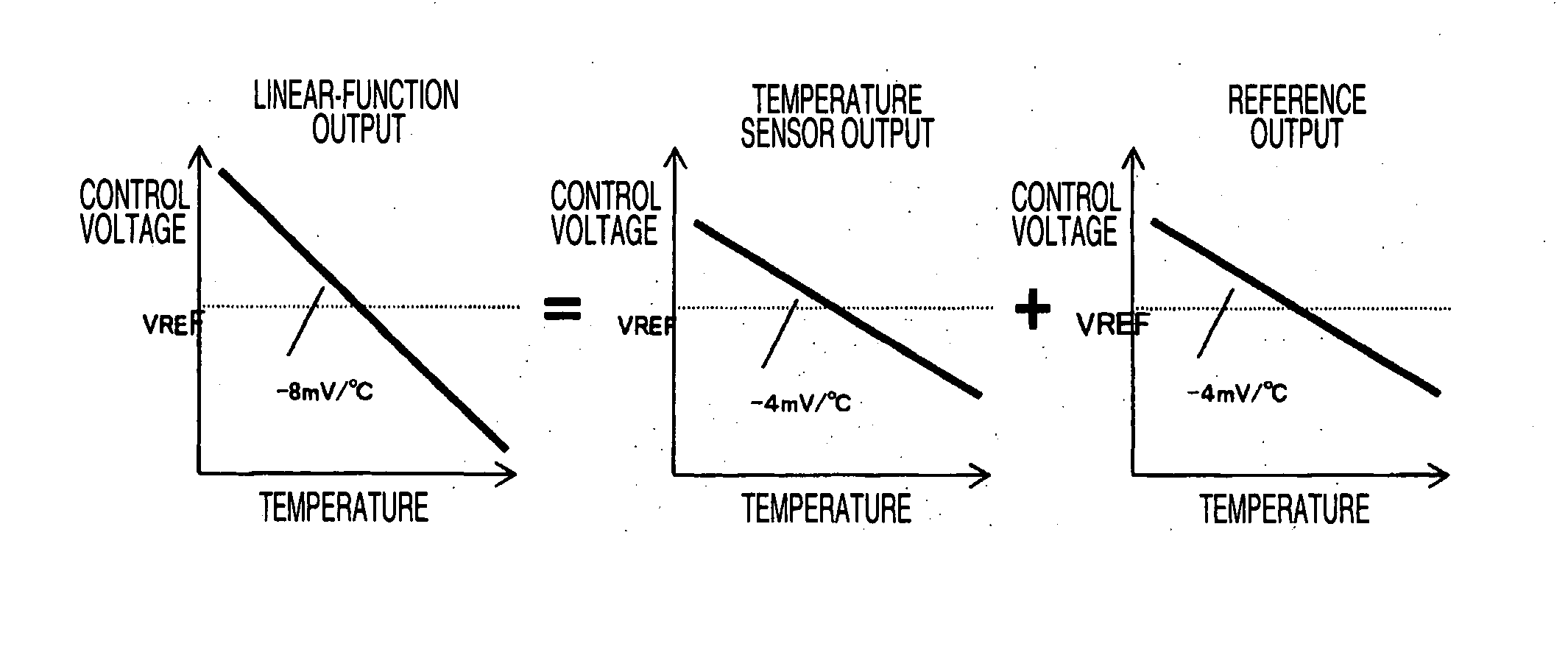
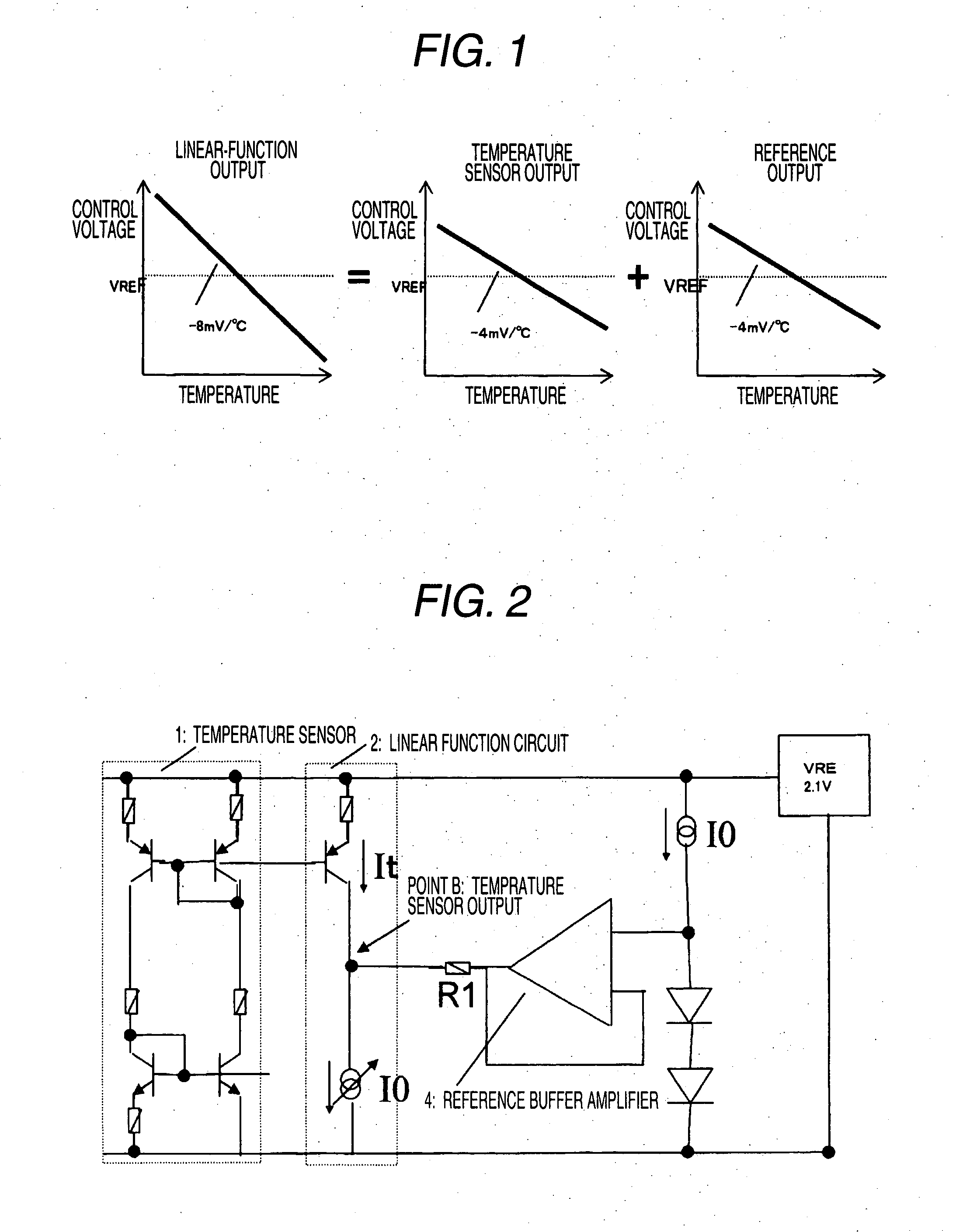
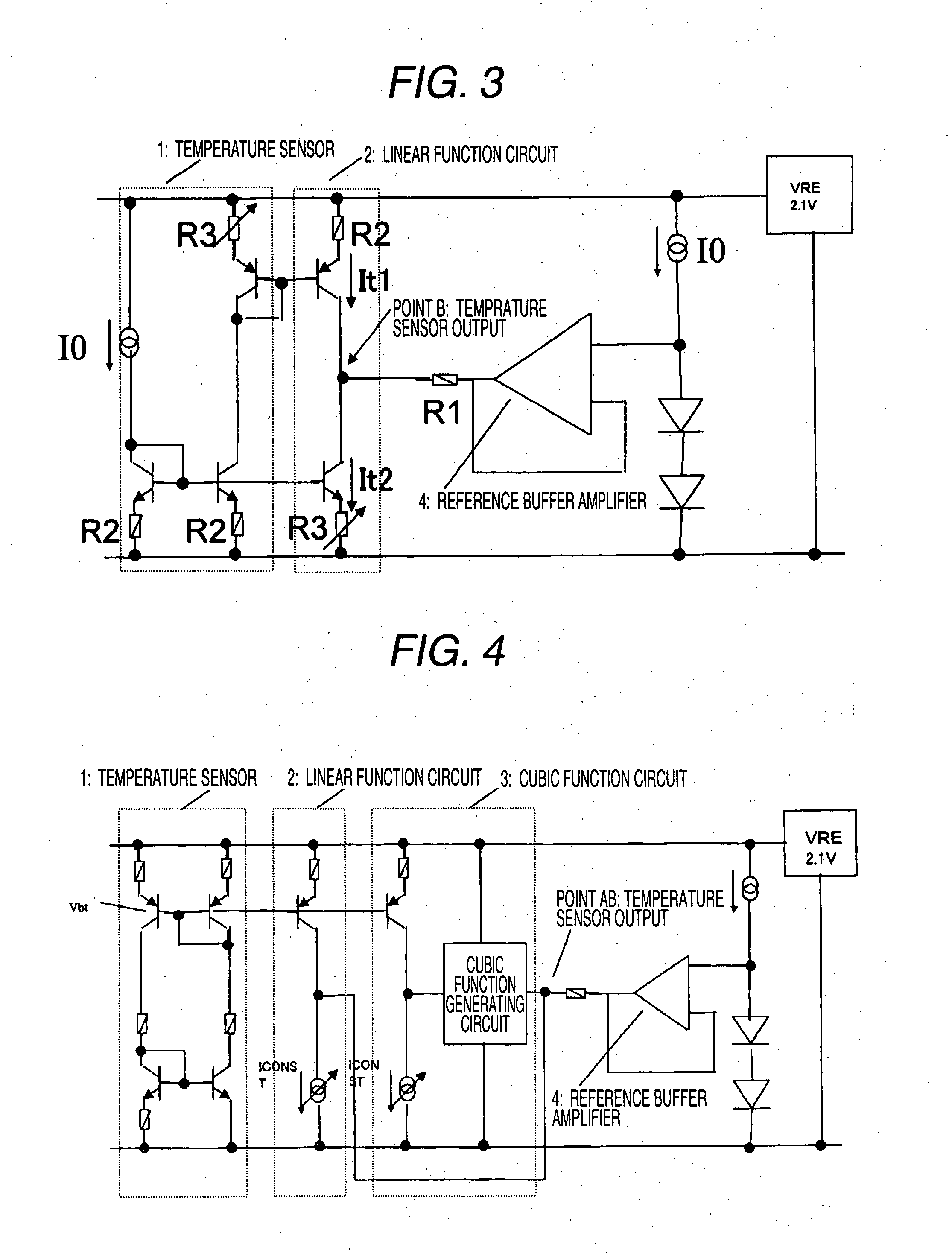
[0041]FIG. 4 is a diagram illustrating a configuration of a control voltage generating circuit in the temperature-compensated crystal oscillator according to a first embodiment of the invention. The control voltage generating circuit shown in the figure includes the linear function generating circuit shown in FIG. 3 and the cubic function circuit 3. Reference voltages of the linear function circuit and the cubic function circuit are generated using the forward voltages of the two diodes connected in series. At this time, it is possible to acquire −8 mV / ° C. at a point AB and reduce the noise by setting the slope of the linear function circuit to −4 mV / ° C. and the temperature characteristic of the reference voltage to −4 mV / ° C.
[0042]FIG. 5 is a diagram illustrating another control voltage generating circuit of the temperature-compensated crystal oscillator according to the first embodiment of the invention. The control voltage generating circuit shown in the figure includes the lin...
second embodiment
[0043]FIG. 6 is a diagram illustrating a configuration of a voltage controlled oscillator in the temperature-compensated crystal oscillator according to a second embodiment of the invention. The voltage controlled oscillator further includes a capacitor capable of applying the control voltage to a drain as well as a gate of an MOS varactor. As shown in the figure, the control voltage (a compensation voltage) is divided into a linear function component generated by the voltage control circuit 1 and a cubic function component generated by the voltage control circuit 2 and is applied to the oscillation control circuit.
[0044]The crystal oscillator shown in FIG. 6 includes an oscillation inverter, a feedback resistor, and a quartz vibrator. The crystal oscillator uses an MOS transistor as a variable capacitor so as to control a frequency of the crystal oscillator and maintains a constant frequency by controlling a gate and a drain of the MOS transistor. It is possible to acquire characte...
third embodiment
[0049]FIG. 10 is a diagram illustrating a configuration of the control voltage generating circuit in the temperature-compensated crystal oscillator according to a third embodiment of the invention. An example in which the resistor is used as a humidity sensor is illustrated in FIG. 10. The linear function and the cubic function are configured on the basis of independent reference voltages. The reference of the linear function is configured using the diode. The reference of the cubic function is configured by resistance dividing. By this configuration, it is possible to reduce the noise of the control voltage at the linear function side.
PUM
 Abstract
Description
Claims
Application Information