Silent food processor

A food processing machine and silent technology, applied in kitchen utensils, home utensils, applications, etc., can solve the problems of limited vibration energy absorption, easy hardening of silicone parts, and difficult installation

Active Publication Date: 2020-05-29
JOYOUNG CO LTD
View PDF24 Cites 7 Cited by
  • Summary
  • Abstract
  • Description
  • Claims
  • Application Information

AI Technical Summary

Problems solved by technology

Although this installation method, the silicone part can absorb part of the vibration and reduce the noise of pulping, but the silicone part is always in a compressed state of being squeezed. During the vibration and extrusion process of the metal inner cup and the outer shell, the amount of deformation is limited, so the absorption The vibration energy is also very limited, and after long-term use, the silicone parts are easy to harden and lose the effect of d

Method used


Image

  • Silent food processor
  • Silent food processor
  • Silent food processor

Examples


Embodiment 1

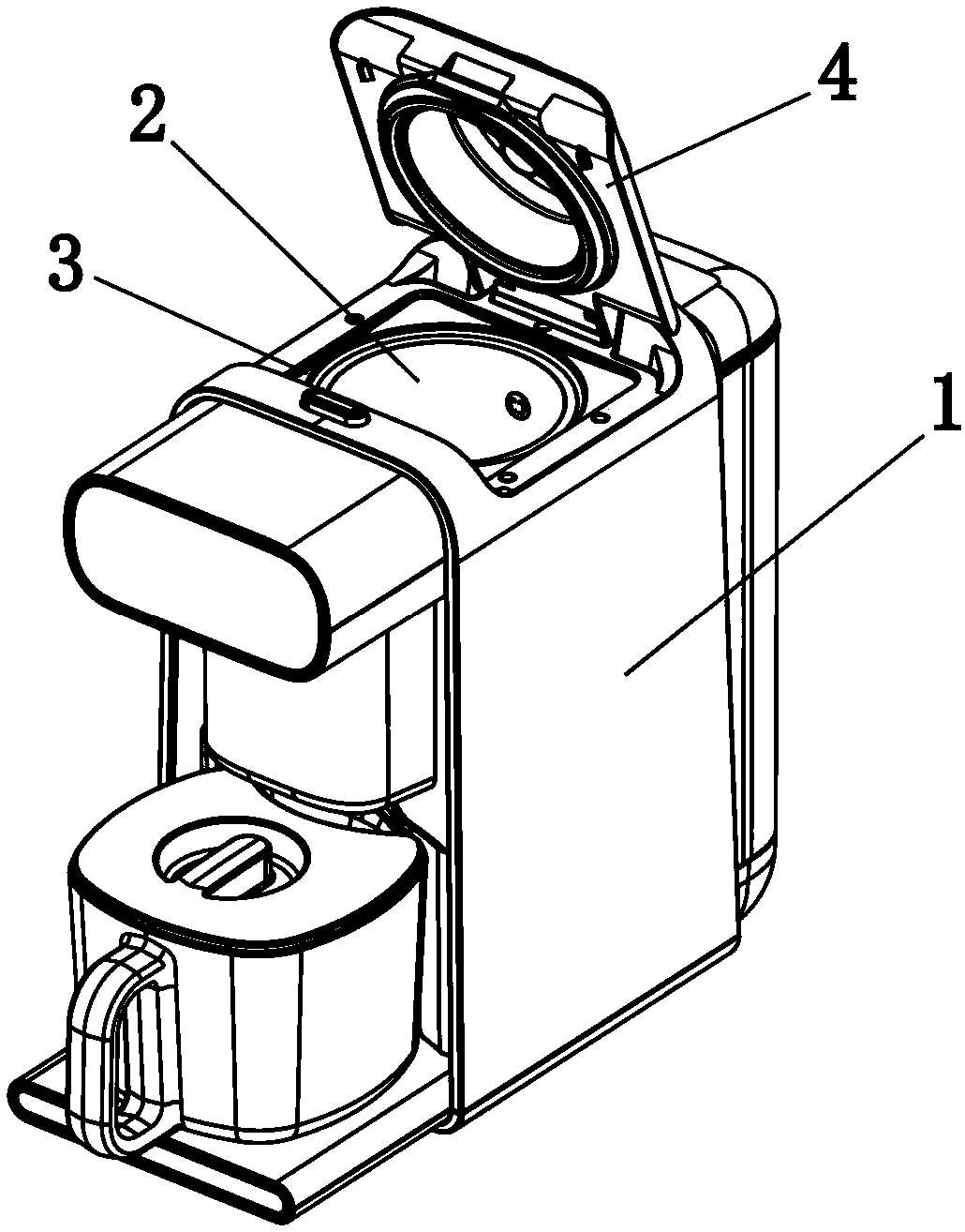
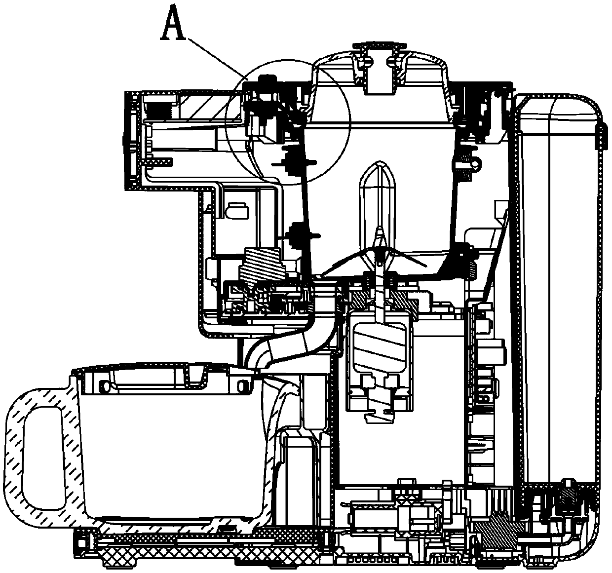
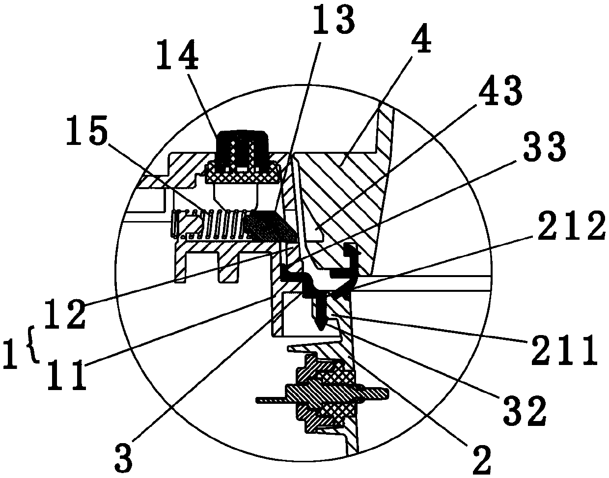
[0038] Such as Figures 1 to 8 Shown is a schematic structural diagram of the first embodiment of the present invention. A food processor, comprising a housing 1 and a cup assembly 2 installed in the housing 1, there is an annular installation gap (not marked in the figure) between the housing 1 and the cup assembly 2, so that the cup The body assembly 2 is not in contact with the housing 1, and flexible connectors 3 are provided at the installation gap to connect the housing 1 and the cup assembly 2 as a whole, wherein one end of the connector 3 is fixed to the housing 1 The other end is fixed on the cup assembly 2, so that the mouth of the cup assembly 2 can float relative to the housing 1.

[0039] In this embodiment, the connecting piece 3 is a connecting ring of silica gel arranged around the cup opening 21 of the cup assembly, the inner ring of the connecting ring is fixed on the cup opening 21, and the outer ring of the connecting ring is fixed on the housing 1 , so t...

Embodiment 2

[0054] Such as Figure 9 Shown is a schematic structural diagram of the second embodiment of the present invention. The difference between this embodiment and the first embodiment lies in that in this embodiment, the connecting ring has a tightening portion 36 that hugs the outer wall of the cup assembly 2 , and the tightening portion 36 forms the inner ring of the connecting ring. At the same time, an outward flange 211 is provided at the mouth of the cup, and a step 361 for supporting the flange 211 is provided on the gripping portion 36 , so that the inner ring of the connecting ring is fixed on the cup assembly 2 . Simultaneously, the outer ring of the connecting ring is provided with an undercut 37, the upper casing 12 and the fixed bracket 11 are fixed by the screw b, and when the upper casing 12 and the fixed bracket 11 are fixed, the outer ring of the connecting ring is clamped so that the undercut 37 is closely attached to the fixed bracket 11, so that the outer ring...

Embodiment 3

[0057] Such as Figure 10 , Figure 11 Shown is a schematic structural view of the third embodiment of the present invention. The difference between the present embodiment and the second embodiment is that in this embodiment, there is no fixed bracket, the casing through hole 100 is provided on the side wall of the casing 1, and the outer ring of the connecting ring is provided with a buckle plug 38. The plug 38 is inserted into the through hole 100 of the housing and snapped onto the outer edge of the through hole 100 of the housing, so that the outer ring of the connecting ring is fixed on the housing 1 . At the same time, a clamp 6 for tightening the clamping portion 36 is provided on the outside of the clamping portion 36 .

[0058] The hoop 6 in this embodiment includes a left hoop 61 and a right hoop 62, and the left hoop 61 and the right hoop 62 are fixed by screws c, so as to tighten the holding part 36 on the outer wall of the cup assembly 2 .

[0059] This embodi...


PUM


Abstract

The invention relates to small kitchen appliances, in particular to a silent food processor. The processor comprises a cup body assembly, a base body which is arranged below the cup body assembly andused for supporting the cup body assembly, and a shell arranged on the outer side of the cup body assembly in a sleeving mode. The water cup is characterized in that the cup body assembly is positioned on the base body, a first shock absorption piece for isolating the cup body assembly from the base body is arranged between the cup body assembly and the base body, the cup body assembly is not in contact with the shell, and a cup opening of the cup body assembly floats relative to the shell. According to the food processor, the cup body assembly is isolated from the base body and does not makecontact with the shell, the cup opening of the cup body assembly floats relative to the shell, vibration energy generated in the working process of the food processor can be absorbed and converted, and noise generated in the working process can be greatly reduced.

Description

technical field [0001] The invention relates to small kitchen appliances, in particular to a silent food processor. Background technique [0002] The existing soybean milk machine cup body on the market includes a shell and a metal inner cup installed in the shell, wherein the bottom wall of the metal inner cup is directly fixed on the base by screws, and the top of the metal inner cup is provided with an outward The horizontal flange is mounted on the top edge of the shell. For this soymilk machine, since the bottom wall of the metal inner cup is in direct contact with the base, and the horizontal flange is in direct contact with the outer shell, the vibration generated by the head of the soymilk machine will be transmitted to the cup body through the coupler during the pulping process. Due to the rigid contact between the metal inner cup and the outer shell and the base, continuous high-frequency impact vibration will be generated between the outer shell and the base an...

Claims


Application Information

Patent Timeline
IPC IPC(8): A47J43/046A47J43/07
CPCA47J43/046A47J43/0716
Inventor 王旭宁明进武吴艳华
Owner JOYOUNG CO LTD
Why Eureka
Try Eureka