Current sampling circuit with temperature drifting compensation function

A current sampling and acquisition circuit technology, applied in the direction of temperature compensation and modification, can solve the problems of large sampling value, multi-single-chip program space and data space, inaccurate power control, etc., and achieve the effect of accurate power control

Active Publication Date: 2014-07-09
INTEMOTION TECH WUXI
View PDF5 Cites 12 Cited by
  • Summary
  • Abstract
  • Description
  • Claims
  • Application Information

AI Technical Summary

Problems solved by technology

However, current sampling basically uses sampling resistors with small impedance. Since the motor current needs to pass through the sampling resistors, the power consumption of the sampling resistors will change according to actual requirements, and the sampling resistors are relatively close to the power module, so it is easier Affected by the ambient temperature, the resistance value of the sampling resistor increases when the temperature rises. Even if the current does not change, the sampling value will also increase accordingly. In the case where the motor driver needs to control the operating power, it will eventually lead to inaccurate power control.
The existing method to solve the temperature drift problem of current sampling is to use software to compensate the sampling value through the detection circuit of the ambient temperature, but this method usually takes up too much program space and data space of the single chip microcomputer

Method used


Image

  • Current sampling circuit with temperature drifting compensation function
  • Current sampling circuit with temperature drifting compensation function

Examples


Embodiment Construction

[0021] The present invention will be further described below in conjunction with drawings and embodiments. It should be understood that the specific embodiments described here are only used to explain the present invention, but not to limit the present invention. In addition, it should be noted that, for the convenience of description, only parts related to the present invention are shown in the drawings but not all content.

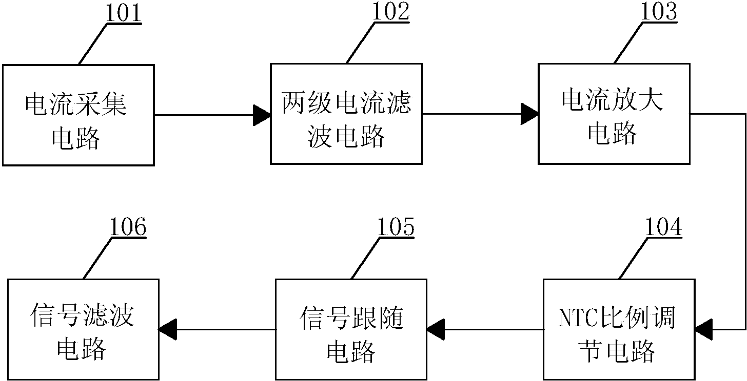
[0022] Please refer to figure 1 as shown, figure 1 A structural block diagram of a current sampling circuit with temperature drift compensation provided by an embodiment of the present invention.

[0023] The current sampling circuit with temperature drift compensation in this embodiment specifically includes: a current acquisition circuit 101 , a two-stage current filter circuit 102 , a current amplification circuit 103 , an NTC ratio adjustment circuit 104 , a signal follower circuit 105 and a signal filter circuit 106 .

[0024] The output end of t...


PUM


Abstract

The invention discloses a current sampling circuit with the temperature drifting compensation function. The current sampling circuit comprises a current sampling circuit, a two-level current filter circuit, a current amplifying circuit, an NTC proportional adjusting circuit, a signal following circuit and a signal filter circuit. According to the current sampling circuit, a negative temperature coefficient thermistor serves as a component for sampling temperature drifting compensation, an integral type proportional feedback type circuit with an operational amplifier and RC filtering integrated is adopted, and finally, the current sampling value does not change along with the change of the temperature of a sampling resistor. On the occasion where a motor driver needs to carry out operation power controlling, accurate power controlling is achieved.

Description

technical field [0001] The invention relates to a current sampling circuit, in particular to a current sampling circuit with temperature drift compensation. Background technique [0002] At present, the calculation of power is basically based on the product of current and voltage. The voltage generally adopts resistance sampling or isolated linear sampling. Because of the large filter capacitor, the general voltage sampling is relatively accurate, and because the voltage sampling uses all It is a resistance value with relatively large impedance, so the power consumption is generally very small, basically no power consumption is generated, and there will be no great change when the ambient temperature changes. However, current sampling basically uses sampling resistors with small impedance. Since the motor current needs to pass through the sampling resistors, the power consumption of the sampling resistors will change according to actual requirements, and the sampling resisto...

Claims


Application Information

Patent Timeline
Patent Type & Authority Applications(China)
IPC IPC(8): G01R1/44
Inventor 娄晶徐永龙陆敏庆
Owner INTEMOTION TECH WUXI
Why Eureka
Try Eureka