Transmission power control method and transmission apparatus

a transmission power and transmission power technology, applied in the field of polar modulation transmitters, can solve the problems of significant transmission power drift, high probability of transmission power drift, and output power in uncompressed mode likely to be discontinuous, so as to improve the accuracy of transmission power control

Inactive Publication Date: 2011-05-31
PANASONIC CORP
View PDF19 Cites 8 Cited by
  • Summary
  • Abstract
  • Description
  • Claims
  • Application Information

AI Technical Summary

Benefits of technology

[0023]It is an object of the present invention to provide a transmission power control method for enabling accurate transmission power control even when there is limit placed upon transmission power control time.
[0025]According to the present invention, it is possible to provide a transmission power control method for enabling improvement in the accuracy of transmission power control by controlling transmission power in a limited predetermined period reliably even when there is limit placed upon timing to complete transmission power control.

Problems solved by technology

However, with conventional transmission apparatuses, when compressed mode (“c-mode”) and uncompressed mode (“u-mode”) change in transmission power control, transmission power drift of maximum 5 dB or greater is likely to occur due to differences in characteristics between modes (i.e. drift due to temperature, drift due to wear, and drift due to load, etc.).
As shown in FIG. 2, output power in uncompressed mode is likely to drift due to various factors, and so, when compressed mode and uncompressed mode change, output power in uncompressed mode is likely to be discontinuous, and, as a result, significant drift in transmission power is likely to occur.
On the other hand, if the time constant for a low-pass filter is set greater, the response of the low-pass filter becomes poorer, and, consequently, accompanying this, the responsivity of feedback control becomes poorer.
There are wireless communication standards that require that transmission power control be completed in a very short period, and so, in practice, the time constant for the low-pass filter cannot be set greater significantly.
Particularly, when the above compressed mode and uncompressed mode change, feedback control with higher speed is needed, and so it becomes more difficult to make the time constant for the low-pass filter greater.
When compressed mode and uncompressed mode change, it is difficult for conventional transmission apparatuses to fulfill the above requirements.

Method used


Image

  • Transmission power control method and transmission apparatus
  • Transmission power control method and transmission apparatus
  • Transmission power control method and transmission apparatus

Examples


embodiment 1

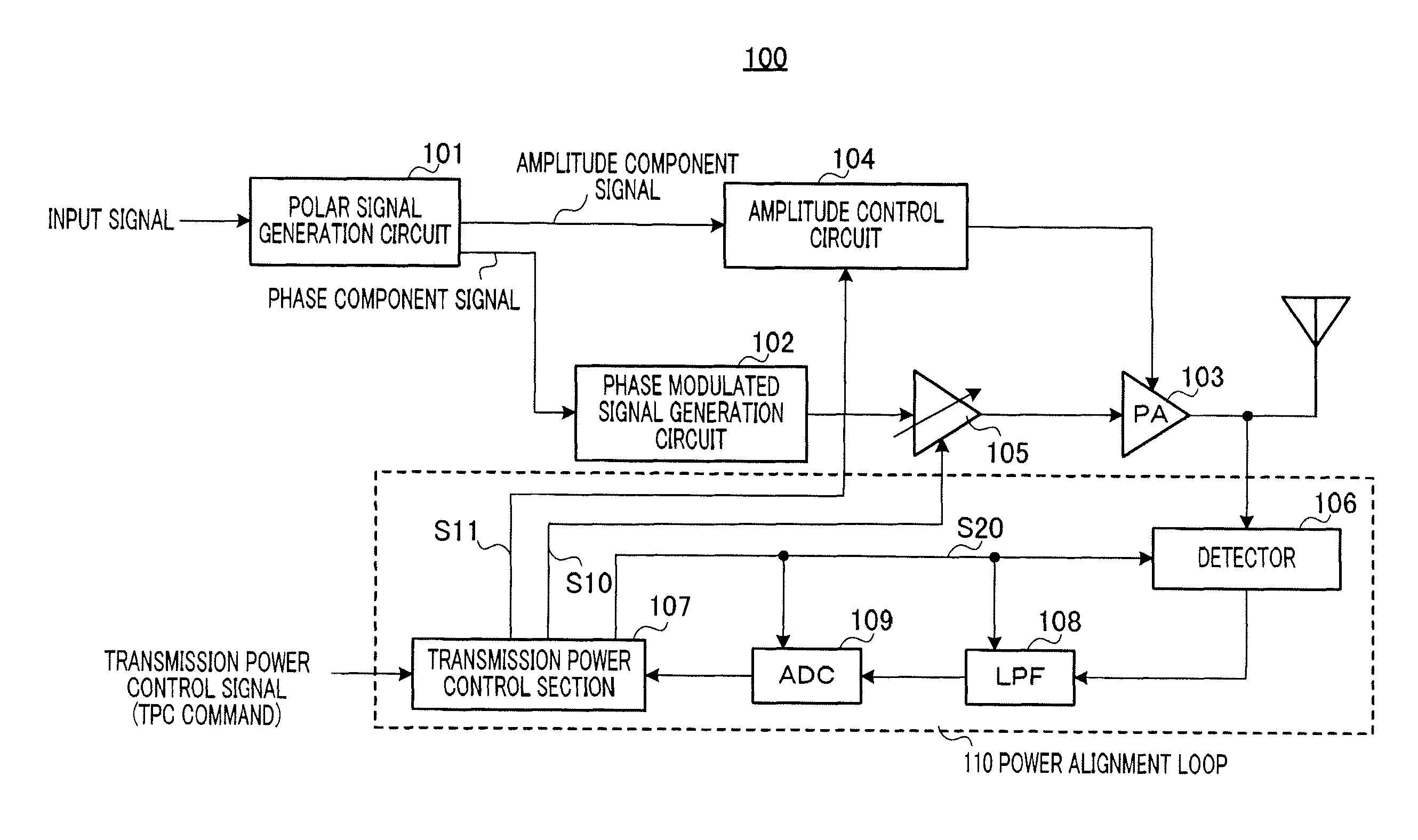
[0052]FIG. 6 shows the configuration of polar modulation transmitter 100 according to Embodiment 1 of the present invention. Polar modulation transmitter 100 of FIG. 6 has polar signal generation circuit 101, phase modulated signal generation circuit 102, power amplifier (PA) 103, amplitude control circuit 104, variable amplifier 105 formed with a variable gain amplifier (VGA) and / or an attenuator, and power alignment loop 110.

[0053]Power alignment loop 110 has detector 106 that detects output power of PA 103, low-pass filter (LPF) 108, analogue-to-digital converter (ADC) 109 and transmission power control section 107.

[0054]Polar signal generation circuit 101 generates amplitude component signals and phase component signals from the input signals. To be more specific, polar signal generation circuit 101 operates according to the input signals from spreading section 110, and generates envelope component signals (i.e. amplitude component signals) containing amplitude information of th...

embodiment 2

[0107]The hardware configuration diagram of the transmission apparatus according to Embodiment 2 of the present invention is the same as in FIG. 6, and so repetition of explanation will be omitted.

[0108]Transmission power control section 107 forces the mode change using transmission power control value ΔP=0, before the symbol boundary where transmission power control value ΔP is set based on transmission power control signals, detects the amount of drift in output power of PA 103 before and after mode changes using average value Pcur before the symbol boundary where transmission power value ΔP is set and before mode changes, and average value Ptar before transmission power value ΔP is set and after mode changes, and, after transmission power control value ΔP is set, corrects target transmission power Ptar—set based on transmission power control value ΔP and the amount of drift.

[0109]FIG. 11 is a flowchart illustrating the operation of polar modulation transmitter 100 when current mo...

embodiment 3

[0122]FIG. 13 shows a configuration of polar modulation transmitter 200 of this embodiment, and, in this figure, the same components as in FIG. 6 will be assigned the same reference numerals.

[0123]Polar modulation transmitter 200 has spreading section 210 and averaging section 220 in addition to the configuration of polar modulation transmitter 100 of FIG. 6.

[0124]Spreading section 210 spreads input signals by spreading codes, and outputs the signals to polar signal generation circuit 101. When generating, for example, an HSUPA (High Speed Uplink Packet Access) signal, spreading section 210 multiplies the DPDCH signal, DPCCH signal, HS-DPCCH signal, E-DPDCH signal, and E-DPCCH signal by spreading codes Cd, Cc, Chs, Ced, and Cec, respectively, adjusts gain factors Beta ratio c (Bc), Beta ratio d (Bd), Beta ratio hs (Bhs), Beta ratio ed (Bed), and Beta ratio ec (Bec), generates an HSUPA signal, and outputs the generated HSUPA signal to polar signal generation circuit 101.

[0125]Averagi...


PUM


Abstract

Even when there is limit placed upon transmission power control time, the transmission power control method enables accurate control transmission power. The transmission power control method includes: a first measuring step of measuring, in a symbol interval before a symbol interval where mode of the power amplifier changes, output power of the power amplifier before mode changes; a first setting step of setting target power of the power amplifier after mode changes based on a measurement result obtained in the first measuring step and a transmission power control signal; a second measuring step of measuring, in the symbol interval where mode of the power amplifier changes, output power of the power amplifier after mode changes, the output power being controlled using the target power set in the first setting step; and a second step of setting corrected target power based on a measurement result obtained in the second measuring step.

Description

CROSS REFERENCE TO RELATED APPLICATIONS[0001]The disclosure of U.S. Patent Application No. 60 / 880,056, filed on Jan. 12, 2007, including the specification, drawings and abstract, is incorporated herein by reference in its entirety.BACKGROUND OF THE INVENTION[0002]1. Field of the Invention[0003]The present invention relates to a polar modulation transmitter and its transmission power control method.[0004]2. Description of Related Art[0005]FIG. 1 shows an example of a typical transmission apparatus using a polar modulation scheme. The transmission apparatus has polar signal generation circuit 1, amplitude control circuit 2, phase modulated signal generation circuit 3 and power amplifier (hereinafter “PA”) 4. In this transmission apparatus, the polar signal generation circuit 1 generates a signal from an input signal (i.e. a transmission modulated signal) signals related to the amplitude and phase of a transmission modulated signal. Amplitude control circuit 2 controls power supply vol...

Claims


Application Information

Patent Timeline
Patent Type & Authority Patents(United States)
IPC IPC(8): H04K1/02H04L25/03H04L25/49H04L27/00
CPCH03F1/0205H03F3/245H04B2001/0416H03F2200/451H03F2200/105
Inventor MATSUOKA, AKIHIKOURUSHIHARA, TOMOYADO, GARYLEE, WAYNE
Owner PANASONIC CORP
Why Eureka
Try Eureka