
A mutual capacitance detection circuit

A detection circuit, mutual capacitance technology, applied in the direction of electrical digital data processing, instruments, calculations, etc., can solve the problem that the input signal-to-noise ratio is easy to drop to 1/1-1/10, aggravates the deterioration of the input signal-to-noise ratio, and common mode suppression Poor ability and other problems, to achieve the effect of improving detection sensitivity, saving area and power consumption, and increasing amplitude

Active Publication Date: 2017-03-15
BYD SEMICON CO LTD
View PDF4 Cites 0 Cited by
  • Summary
  • Abstract
  • Description
  • Claims
  • Application Information

AI Technical Summary

Problems solved by technology

[0004] At the same time, when touching with human hands, there is a common-mode noise leakage path due to the lack of common ground between the human body and the detection system. Therefore, capacitive detection is an electrical open detection (all references are not based on the same ground reference). Poor common mode rejection
When human touch is performed, the self-capacitance change due to the proximity of the human hand to the detection sensor is generally 10-100 times the mutual capacitance change. Common-mode noise is released through this self-capacitance coupling. In some amplifiers with poor common-mode noise , the input signal-to-noise ratio can easily be reduced to 1 / 1-1 / 10
At the same time, technological evolution and the use of the stylus have aggravated the deterioration of the input signal-to-noise ratio and increased the requirements for the detection signal-to-noise ratio. In order to solve these problems, if the common mode noise of the amplifier is reduced and the detection chip itself performs ASP (Analog Signal Process, analog signal processing) or DSP (Digital Signal Process, digital signal processing) filtering and other methods will bring high system cost

Method used


Image

  • A mutual capacitance detection circuit
  • A mutual capacitance detection circuit
  • A mutual capacitance detection circuit

Examples


Embodiment Construction

[0032] Embodiments of the present invention are described in detail below, examples of which are shown in the drawings, wherein the same or similar reference numerals designate the same or similar elements or elements having the same or similar functions throughout. The embodiments described below by referring to the figures are exemplary only for explaining the present invention and should not be construed as limiting the present invention.

[0033] In describing the present invention, it should be understood that the terms "longitudinal", "transverse", "upper", "lower", "front", "rear", "left", "right", "vertical", The orientation or positional relationship indicated by "horizontal", "top", "bottom", "inner", "outer", etc. are based on the orientation or positional relationship shown in the drawings, and are only for the convenience of describing the present invention and simplifying the description, rather than Nothing indicating or implying that a referenced device or elem...


PUM


Abstract

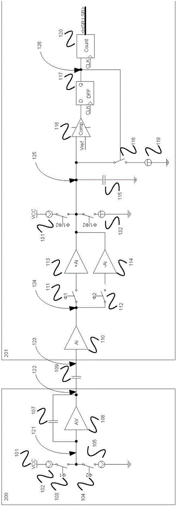
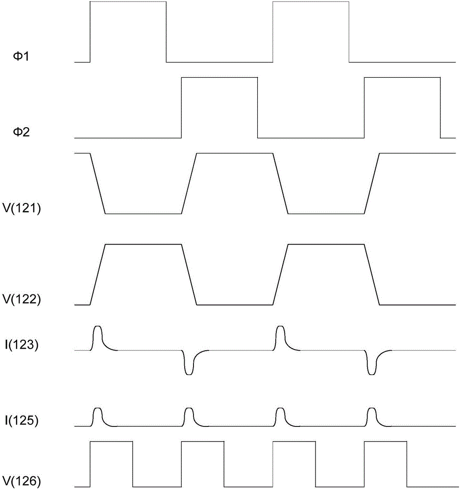
A mutual-capacitance detection circuit and a mutual-capacitance detection array are provided. The mutual-capacitance detection circuit comprises: a first capacitor; a limited current transmitting module, connected with an input end of the first capacitor and configured to control the first capacitor to output a current signal having an alternate positive and negative amplitude; and a receiving module, connected with an output end of the first capacitor and configured to output a digital level pulse signal according to the amplitude of the current signal output from the first capacitor, in which a width of the digital level pulse signal is positively related with the amplitude of the current signal output from the first capacitor.

Description

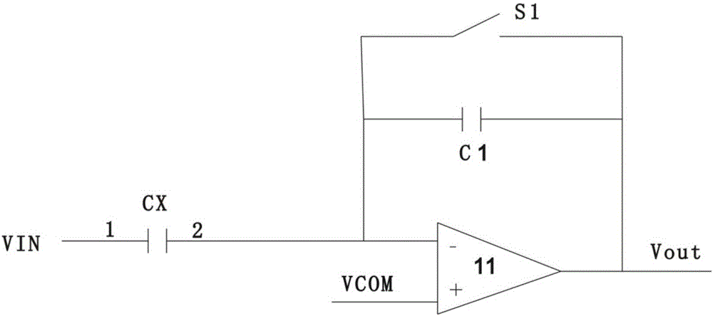
technical field [0001] The invention relates to the technical field of circuit design, in particular to a mutual capacitance detection circuit used on a capacitive touch device. Background technique [0002] Among existing capacitive touch detection devices, devices based on mutual capacitance detection can realize real multi-touch, but compared with self-capacitance detection, mutual capacitance detection needs to face problems such as low input signal-to-noise ratio and high system cost. [0003] figure 1 It is an existing mutual capacitance detection circuit, and the detection circuit calculates the coordinates of each touch point by detecting the power change data of the two-dimensional capacitance of the touch screen when the finger is touched. Its working principle is as follows: When there is no touch, the external excitation VIN jumps from one voltage V1 to another voltage V2, and by controlling the on and off of the first switch S1, the negative feedback of the fir...

Claims


Application Information

Patent Timeline
Patent Type & Authority Patents(China)
IPC IPC(8): G06F3/044
CPCG06F3/04182G06F3/044
Inventor 丁龙张杰杨云
Owner BYD SEMICON CO LTD
Learn More