
Reflection type differential strength modulating optical fiber sensing device and method thereof

A differential strength, optical fiber sensing technology, applied in the direction of using optical devices to transmit sensing components, optical waveguide coupling, etc. The linear measurement range is restricted by each other, so as to improve the signal-to-noise ratio and improve the axial resolution.

Inactive Publication Date: 2012-06-06
HARBIN ENG UNIV
View PDF0 Cites 0 Cited by
  • Summary
  • Abstract
  • Description
  • Claims
  • Application Information

AI Technical Summary

Problems solved by technology

[0003] Yang Huayong et al. (Yang Huayong, Lu Haibao, Xu Tao, et al. Analysis of several three-fiber sensors with compensation function. Journal of National University of Defense Technology, 2002, 24(1): 105-108) studied the core diameter inequality, equal core dislocation formula And three types of three-fiber reflective optical fiber sensors with equal core and unequal spacing, which effectively suppress the influence of light intensity fluctuations and electronic noise, and improve the linear range of the system to a certain extent, but they have not effectively improved the system. Resolution and sensitivity, and there is a large measurement "dead zone"
[0004] The MTI-2100 series reflective optical fiber sensor of MTI Company in the United States adopts multi-fiber distribution probes such as irregular distribution, hemispherical distribution and concentric distribution, which greatly improves the resolution and sensitivity of the system, and there is a small dead zone, but There is still a contradiction between system resolution and linear measurement range restricting each other

Method used


Image

  • Reflection type differential strength modulating optical fiber sensing device and method thereof
  • Reflection type differential strength modulating optical fiber sensing device and method thereof
  • Reflection type differential strength modulating optical fiber sensing device and method thereof

Examples


Embodiment Construction

[0020] The present invention is described in more detail below in conjunction with accompanying drawing example:

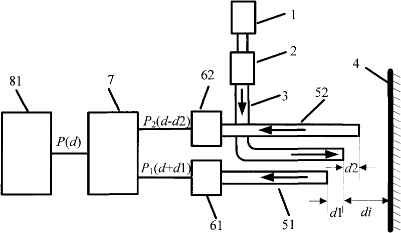
[0021] combine Figure 1~4 , the present invention provides a reflective differential intensity modulation optical fiber sensing device, comprising a light source 1, an optical fiber coupler 2 placed at the emitting end of the light source, an emitting optical fiber 3, and a reflector 4, respectively arranged on both sides of the emitting optical fiber 3 , and the misalignment of the receiving end face and the emitting end face of the emitting fiber 3 is respectively the receiving optical fibers 51 and 52 of d1 and d2, and the photodetector 61 placed at the emitting end of the receiving optical fiber 51 and the photodetector 62 placed at the emitting end of the receiving optical fiber 52, the computer Processing system 8, wherein the powers of the axial response signals received by photodetector 61 and photodetector 62 are P 1 (d, d1) and P 2 (d, d2), it is char...


PUM


Abstract

The invention aims to provide reflection type differential strength modulating optical fiber sensing device and method thereof. The device comprises a light source, an optical fiber coupler, an optical fiber, a reflector, a photoelectric detector, a computer processing system and a differential subtractive processing system. The invention ensures the front slope resolution and linear range of axial response, greatly improves the dead area range of the device and the back slope resolution of axial response, and obviously strengthens the anti-jamming capability and linear range of the system.

Description

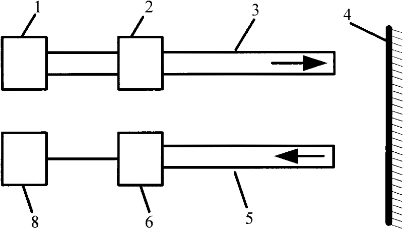
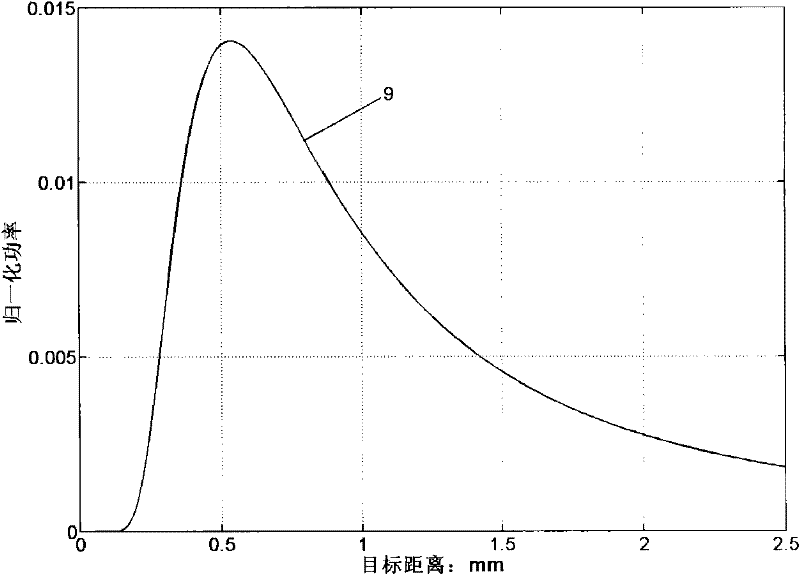
technical field [0001] The invention relates to a sensing device, and the invention also relates to a sensing method, in particular to a sensing device and method applied to optical fiber sensing and photoelectric detection. Background technique [0002] The basic principle of the traditional reflective fiber optic sensor is as follows: figure 1 As shown, the light emitted by the light source 1 is coupled by the coupler 2, enters the emitting optical fiber 3, and then passes through the emitting optical fiber 3 to the reflector 4, and the reflected light is collected by the receiving optical fiber 5 and sent to the photodetector 6. The processing of the processing unit 8 can obtain the change of the distance between the end face of the optical fiber and the measured surface. The sensor is characterized by compact structure, simple principle, flexible design, low price, etc., so it has been successfully applied in the measurement of many physical quantities (such as displace...

Claims


Application Information

Patent Timeline
Patent Type & Authority Patents(China)
IPC IPC(8): G01D5/353G02B6/26
Inventor 单明广钟志彭欢
Owner HARBIN ENG UNIV
Learn More