Boring cutter

A kind of boring tool and tool holder technology, which is applied to the boring tool field for milling machine boring, can solve the problems such as the equipment cannot complete the processing task and exceeds the processing range, and achieves the effect of small investment, wide processing range and high processing efficiency

Inactive Publication Date: 2014-07-16
XINXING DUCTILE IRON PIPES CO LTD
View PDF6 Cites 2 Cited by
  • Summary
  • Abstract
  • Description
  • Claims
  • Application Information

AI Technical Summary

Problems solved by technology

However, because the center distance between the two holes exceeds the processing range of the equipment, the existing equipment cannot complete the processing task

Method used


Image

  • Boring cutter

Examples


Embodiment Construction

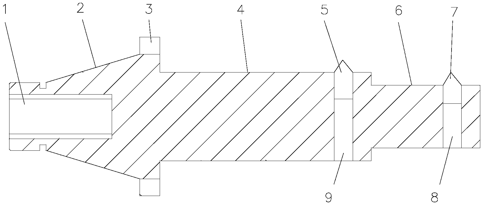
[0009] Such as figure 1 Shown, the present invention comprises cutter bar and cutting tool, and the left end of cutter bar is cone 2, and cone 2 cooperates with the cone of boring machine main shaft hole, and the axle center of cone 2 has internally threaded hole 1, and the connecting rod of boring machine main shaft Through the metric thread connection, the tension effect is played. The right end of the tool bar is the shoulder shaft 4, 6, and the right end of the shoulder shaft 4, 6 has radial left and right tool fixing holes 9, 8 respectively, and the left and right tool fixing holes 9, Fix the left and right boring cutters 5,7 respectively in 8.

[0010] The junction of the cone 2 and the shoulder shafts 4, 6 has a groove 3 with a larger diameter than the large end of the cone 2, and the groove 3 cooperates with the protrusion of the boring machine to form a rigid connection.


PUM


Abstract

The invention relates to a boring cutter. The boring cutter comprises a cutter bar and a cutter body. A conical body is arranged at the left end of the cutter bar and is matched with another conical body of a main shaft hole of a boring machine, and an inner threaded hole is formed in the axis of the conical body. The conical body is connected with a connecting rod of a main shaft of the boring machine through a metric thread, so that the tensioning effect is achieved. Shoulder shafts are arranged at the right end of the cutter bar, a left radial cutter body fixing hole and a right radial cutter body fixing hole are formed in the right ends of the shoulder shafts respectively, and a left boring cutter and a right boring cutter are fixed in the left cutter body fixing hole and the right cutter body fixing hole respectively. The boring cutter is simple in structure, and can carry out hole diameter machining beyond the machining range of equipment.

Description

technical field [0001] The invention relates to a cutting tool, in particular to a boring tool for boring a milling machine. Background technique [0002] The motor base is processed after the welding is completed. In order to ensure the parallelism between the aperture and the bottom surface of the base and the coaxiality between the two holes, it must first be marked by a fitter and pre-drilled. Boring processing, because the center distance between two holes exceeds the range of equipment stroke processing, it brings great difficulties to machining. [0003] The traditional processing method is to process the two apertures at one time, so that the processed workpiece has good coaxiality and high precision. However, because the center distance between the two holes exceeds the processing range of the equipment, the existing equipment cannot complete the processing task. Contents of the invention [0004] In order to overcome the disadvantages of the prior art, the pres...

Claims


Application Information

Patent Timeline
Patent Type & Authority Applications(China)
IPC IPC(8): B23B27/00
CPCB23B27/00
Inventor 李国文
Owner XINXING DUCTILE IRON PIPES CO LTD
Why Eureka
Try Eureka