Wheel deburring device

A deburring and wheel technology, applied in the direction of grinding machines, metal processing equipment, grinding/polishing equipment, etc., can solve the problems of poor deburring effect, low brush line speed, affecting production efficiency, etc., to achieve comprehensive functions and adaptability Wide range, safe and stable performance

Active Publication Date: 2014-07-16
CITIC DICASTAL
View PDF6 Cites 21 Cited by
  • Summary
  • Abstract
  • Description
  • Claims
  • Application Information

AI Technical Summary

Problems solved by technology

In the production process, brushes need to be replaced frequently according to the size of the wheel, which is not only time-consuming and laborious, but also seriously affects production efficiency.
At the same time, when the traditional large disc brush deburrs, the linear speed of the brush is low at the position close to the base of the flange, and the deburring effect is often not good.

Method used


Image

  • Wheel deburring device
  • Wheel deburring device
  • Wheel deburring device

Examples


Embodiment Construction

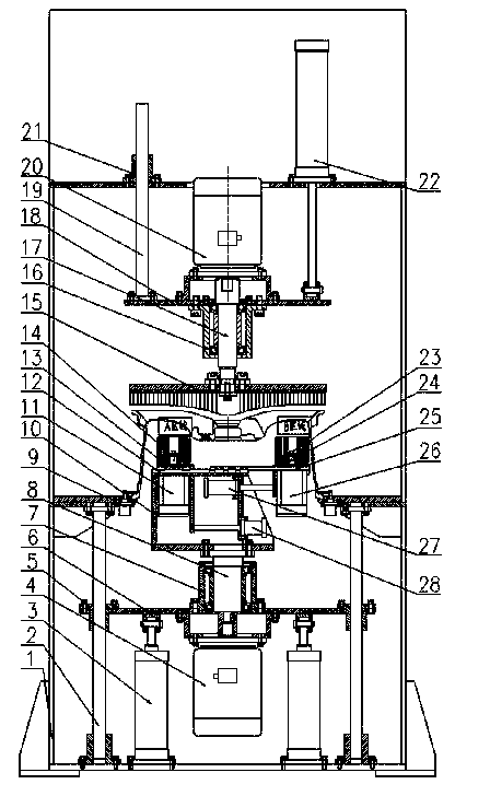
[0018] The details and working conditions of the specific device proposed according to the present invention will be described below in conjunction with the accompanying drawings.

[0019] The device consists of frame 1, lower guide column 2, lifting cylinder 3, lower motor 4, lower guide sleeve 5, lower lifting plate 6, lower bearing seat 7, lower shaft 8, clamp 9, turntable 10, left motor 11, Guide rail Ⅰ12, left slide plate 13, left brush 14, upper brush 15, upper bearing seat 16, upper shaft 17, upper lifting plate 18, upper guide column 19, upper motor 20, upper guide sleeve 21, lifting cylinder 22, right hair Brush 23, right slide plate 24, guide rail Ⅱ 25, right motor 26, servo electric cylinder Ⅰ 27 and servo electric cylinder Ⅱ 28, four lower guide columns 2 and two lifting cylinders 3 are fixed on the bottom plate of frame 1; The four lower guide sleeves 5 matched with the column 2 are fixed on the lower lifting plate 6; the output ends of the two lifting cylinders 3...


PUM


Abstract

The invention discloses a wheel deburring device which is composed of a machine frame, an air cylinder, motors, brushes, servo electric cylinders and the like. In the use process, a wheel is placed on a clamp, the position of the right brush and the position of the left brush are automatically adjusted by means of the servo electric cylinder I and the servo electric cylinder II according to the detected appearance size of the wheel and the detected size of a flange plate; then, the left brush and the right brush are lifted by the lifting air cylinder through a lower guide column so that the left brush and the right brush can make contact with a back cavity of the wheel; when the left motor and the right motor drive the left brush and the right brush to rotate respectively, the lower motor enables the left brush and the right brush to rotate on the different radiuses of the wheel through a lower shaft; meanwhile, the lifting air cylinder enables the upper motor to drive the upper brush to rotate when enabling the upper brush to fall to make contact with the front face of the wheel. When the wheel deburring device is used, the position of the left brush and the position of the right brush can be automatically adjusted so as to meet the requirements of the wheels in different sizes for deburring, and burrs at different positions of the back cavity of the wheel can be removed at the same linear speed.

Description

technical field [0001] The invention relates to a deburring device, in particular to a deburring device for auto parts. Background technique [0002] In the production process of aluminum alloy wheels, deburring after machining is one of the essential processes. Most enterprises are producing in mixed lines, that is, wheels of different sizes and different wheel widths are circulating on the production line at the same time. In the production process, the brushes need to be replaced frequently according to the size of the wheels, which not only takes time and effort, but also seriously affects the production efficiency. At the same time, when the traditional large disk brush deburrs, the linear speed of the brush is low at the position close to the base of the flange, and the deburring effect is often not good. The device of the invention can not only automatically adjust the positions of the right brush and the left brush to meet the deburring requirements of wheels of di...

Claims


Application Information

Patent Timeline
Patent Type & Authority Applications(China)
IPC IPC(8): B24B9/04
CPCB24B9/04
Inventor 薛博文郭建东王永宁朱志华李昌海
Owner CITIC DICASTAL
Why Eureka
Try Eureka