Binocular wet sludge drying equipment

A wet sludge and equipment technology, applied in the field of urban sewage sludge drying, can solve the problems of low heat exchange efficiency, high dust volume, large heat loss, etc., and achieve the effect of improving thermal efficiency

Inactive Publication Date: 2014-07-16
CHONGQING UNIV
View PDF3 Cites 28 Cited by
  • Summary
  • Abstract
  • Description
  • Claims
  • Application Information

AI Technical Summary

Problems solved by technology

Existing drying technologies and equipment such as drum sludge drying equipment and multi-stage disc sludge drying equipment mainly rely on sludge back-mixing, and fluidized bed sludge drying equipment relies on convective heat transfer. They all have the disadvantages of low heat exchange efficiency, large heat loss, and high dust content; the rotary shaft sludge drying equipment is favored by the field of sludge drying due to its sufficient heat exchange and low dust content.

Method used


Image

  • Binocular wet sludge drying equipment
  • Binocular wet sludge drying equipment
  • Binocular wet sludge drying equipment

Examples


Embodiment 1

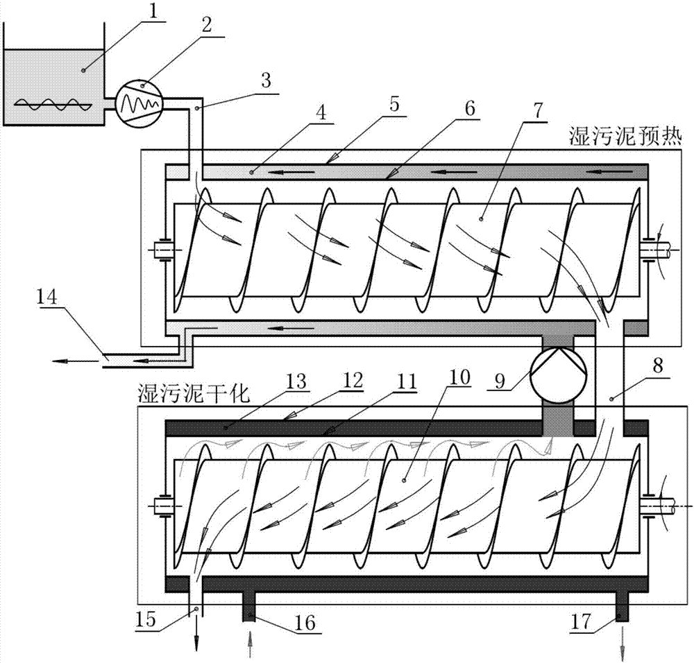
[0014] The double-tube wet sludge drying equipment involved in this embodiment is as follows: figure 1 As shown: the equipment includes a sludge pump 2, a preheating cylinder liner 6, a pipe 3 connecting the sludge pump and the preheating cylinder liner, a preheating cylinder interlayer 4, a sludge pushing shaft I7, and a drying cylinder liner 11 , the sludge feeding pipe 8 connecting the inner tank of the preheating cylinder and the inner tank of the drying cylinder, the interlayer of the drying cylinder 13, the sludge pushing shaft II 10, the high-temperature fan 9 connecting the interlayer of the preheating cylinder and the inner tank of the drying cylinder, the preheating Heat cartridge shell 5 and drying cartridge shell 12.

[0015] The wet sludge 1 is transported by the sludge pump 2 to the liner 6 of the preheating cylinder, pushed toward the wet sludge outlet of the preheating cylinder under the action of the sludge pushing shaft I7, and enters the drying cylinder thro...

Embodiment 2

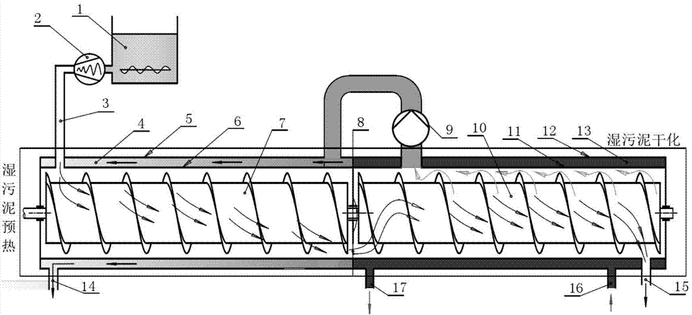
[0019] The double-tube wet sludge drying equipment involved in this embodiment is as follows: figure 2 As shown, the wet sludge preheating cylinder and the wet sludge drying cylinder are connected as a coaxial body, the preheating cylinder liner 6 and the drying cylinder liner 11 are separated by an intermediate layer, and the preheating cylinder interlayer 4 and The interlayer 13 of the drying cylinder is also separated by the above-mentioned middle spacer, and the middle spacer is provided with a sludge discharge channel 8 .

Embodiment 3

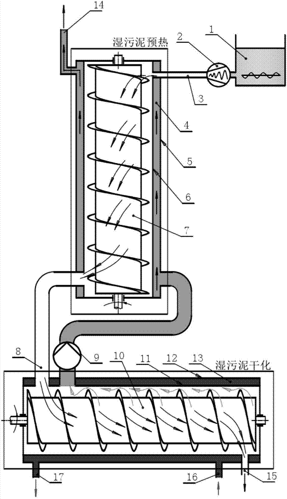
[0021] The double-tube wet sludge drying equipment involved in this embodiment is as follows: image 3 As shown, the wet sludge preheating cylinder is arranged vertically, and the wet sludge drying cylinder is arranged horizontally.

[0022] The preheating stage and water evaporation stage in the wet sludge drying process of the above embodiment are carried out in two devices respectively, which improves the drying efficiency, and at the same time, the energy of the high-temperature steam generated in the water evaporation stage is used for the preheating stage The required heat improves energy efficiency. At the same time, this energy recovery method without intermediate links also greatly simplifies the entire drying system.


PUM


Abstract

The invention discloses binocular wet sludge drying equipment which is composed of a sludge pump (2), a wet sludge preheating drum, a wet sludge drying drum and a pipeline, wherein the wet sludge preheating drum is connected with the sludge pump (2) through the pipeline (3); the wet sludge drying drum is connected with the wet sludge preheating drum through a sludge blanking channel (8). According to the invention, steam latent heat for sludge drying is sufficiently utilized, and wet sludge entering into the wet sludge drying drum can rapidly enter into water evaporation stage because the steam latent heat preheats the wet sludge, so that the efficiency of sludge drying is improved, and energy conservation and emission reduction of sludge drying is realized; the wet sludge preheating drum is used as a direct heat exchanger between high-temperature steam and the wet sludge without auxiliary equipment such as a heat exchange fan, thereby improving the efficiency of heat exchange and simplifying the whole drying system.

Description

technical field [0001] The invention belongs to the technical field of urban sewage sludge drying, in particular to a double-tube wet sludge preheating and drying equipment, and particularly relates to its energy recovery and utilization mode. Background technique [0002] With the development of my country's economy, the discharge of urban wastewater is increasing day by day, and the production capacity of sludge plants has also been greatly increased. Sludge treatment and disposal have gradually become the focus of attention at home and abroad. At present, the sludge disposal methods in my country mainly include sanitary landfill, composting, direct land use and incineration. The moisture content of sludge is the key to restricting sludge disposal. The moisture content of sludge from 95% to 60% is the starting point of landfill and composting, and from 95% to 50% is the starting point of incineration. The traditional mechanical dehydration method can reduce the moisture c...

Claims


Application Information

Patent Timeline
Patent Type & Authority Applications(China)
IPC IPC(8): C02F11/12
Inventor 周杰王时龙尹梦骄任磊胡宗延
Owner CHONGQING UNIV
Why Eureka
Try Eureka