Ceramic kiln burner

A ceramic kiln and burner technology, which is applied in the direction of burner, gas fuel burner, combustion type, etc., can solve the problem of not being able to observe the flame state in the center, achieve installation and durability, avoid energy waste, and facilitate installation Effect

Active Publication Date: 2014-07-16
SHANGHAI YIDE TECH
View PDF6 Cites 6 Cited by
  • Summary
  • Abstract
  • Description
  • Claims
  • Application Information

AI Technical Summary

Problems solved by technology

[0005] In addition, the existing fire viewing devices for burners in ceramic kilns are usually arranged in the non-central part of the burner, so the flame condition in the central part cannot be observed

Method used


Image

  • Ceramic kiln burner
  • Ceramic kiln burner
  • Ceramic kiln burner

Examples


Embodiment Construction

[0048] Preferred embodiments of the present invention will be described in detail below in conjunction with the accompanying drawings, so as to better understand the purpose, features and advantages of the present invention. It should be understood that the embodiments shown in the drawings are not intended to limit the scope of the present invention, but only to illustrate the essence of the technical solutions of the present invention.

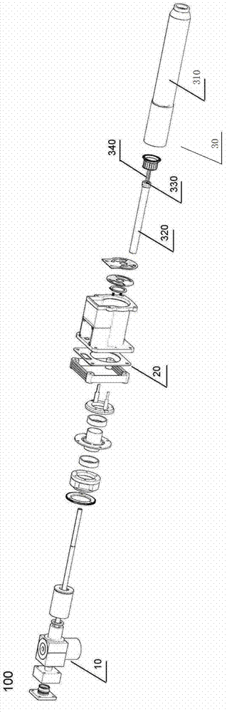
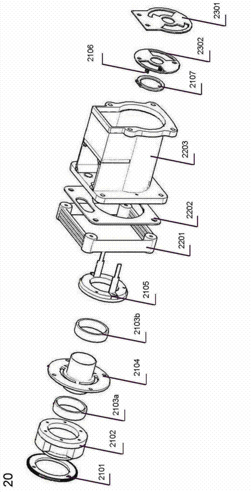
[0049] figure 1 An exploded perspective view of a ceramic kiln burner according to an embodiment of the present invention is shown, wherein the control device of the burner is not shown. Such as figure 1As shown, the ceramic kiln burner 100 of the present invention includes a fire viewing device 10, an air regulating device 20, a combustion device 30, and a control device (not shown). Wherein, the air regulating device 20 adjusts the amount of air intake according to the amount of gas entering the burner or according to the required furnac...


PUM


Abstract

The invention discloses a ceramic kiln burner. The burner comprises a controller, an air adjusting device, a fire observing device and a nozzle. The nozzle comprises an air distribution head and a nozzle sleeve. The nozzle sleeve is an integrated member composed of a premixing chamber, a combustor and an accelerating ring. The air distribution head is positioned at a junction, between the premixing chamber and the combustor, in the premixing chamber. The air adjusting device comprises a transmission mechanism and air valve blades. During working, a fixed air valve blade is fixed and motionless, and a rotating air valve blade can rotate relative to the fixed air valve blade to adjust supply air rate of the ceramic kiln burner. The burner further comprises a flameout protection device arranged in the combustor and a tempering protection device arranged in a vortex tube of the air distribution head. The burner can burn stably, has impulsive force, and is high in heat efficiency, capable of accurately adjusting the supply air rate to achieve an optimum air-fuel ratio and capable of effectively preventing flameout and tempering.

Description

technical field [0001] The present invention relates to a ceramic kiln burner. Background technique [0002] Among the existing ceramic kiln burners, the burners without a premix chamber are called post-mix burners. Such burners have insufficient combustion, low thermal efficiency, and produce more CO. The other is a burner with a premixed chamber, called a premixed or fully premixed burner, whose premixed chamber and combustion chamber are separate components. This kind of burner has the disadvantages of easy flame separation, easy flameout, erratic flame without momentum, and difficult detection of flame ions. In addition, most of the existing ceramic kiln burners are post-mix burners in which the gas distribution head (also known as the gas distribution flower basket or burning head) is mainly made of metal materials such as stainless steel. In this kind of burner structure, the gas distribution head made of metal material is easily oxidized and burned at high temperatu...

Claims


Application Information

Patent Timeline
Patent Type & Authority Applications(China)
IPC IPC(8): F23D14/02F23D14/46F23D14/62F16K1/18F16K31/53F16K31/04
Inventor 张子羿
Owner SHANGHAI YIDE TECH
Why Eureka
Try Eureka