
Heat supply pipe network hydraulic balance automatic adjustment method

An automatic adjustment and hydraulic balancing technology, applied in space heating and ventilation details, household heating, heating methods, etc., can solve the problems of time-consuming, labor-intensive, labor-intensive, deteriorating heating quality, and lag in effect, reducing labor burden, Intuitive and reliable effects

Inactive Publication Date: 2014-07-16
CHINA UNIV OF PETROLEUM (EAST CHINA)
View PDF5 Cites 10 Cited by
  • Summary
  • Abstract
  • Description
  • Claims
  • Application Information

AI Technical Summary

Problems solved by technology

[0002] With the further improvement of energy-saving requirements, room temperature compliance requirements and refined heating management requirements, the demand for scientific and rational adjustment of the hydraulic balance of the heating network is becoming more and more intense. Due to the distance from the heat source, the newness of the residential buildings, and the insulation effect, the indoor temperature of some users cannot fully meet the heating standards.
The imbalance of hydraulic working conditions is common in the heating pipe network, often resulting in overheating at the near end and overcooling at the far end, which not only reduces the efficiency of the heating system but also deteriorates the quality of heating supply. At the same time, energy consumption and operating costs increased badly
[0003] In the absence of a flow meter, the opening of the branch line valve and the valve at the head of the building is generally adjusted step by step through the indoor temperature feedback from the room temperature monitoring tables set in different areas, thereby gradually adjusting the hydraulic balance of the branch line. The method only refers to the data of the indoor temperature, and cannot realize the "adjustment on demand" of the heat, and needs to adjust each valve repeatedly, the effect is lagging, time-consuming, labor-intensive, labor-intensive and energy-consuming, and sometimes the balance cannot be achieved even after multiple adjustments

Method used


Image

  • Heat supply pipe network hydraulic balance automatic adjustment method
  • Heat supply pipe network hydraulic balance automatic adjustment method

Examples


Embodiment Construction

[0026] Embodiments of the present invention will be described below in conjunction with the accompanying drawings.

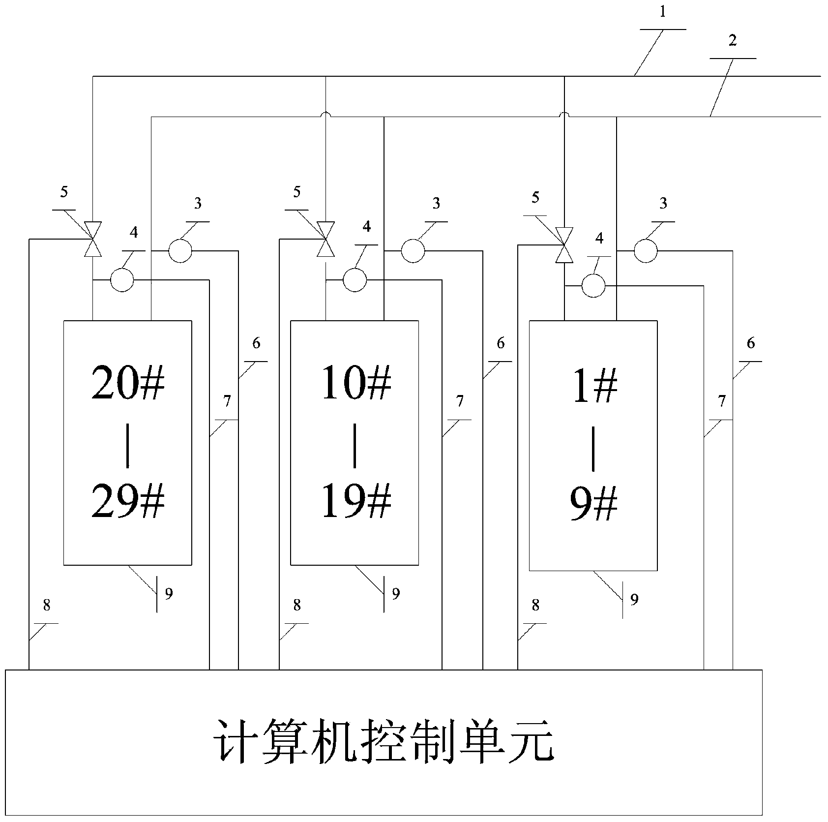
[0027] figure 1 Suppose it is a heating schematic diagram of a residential area, which abstracts the entire residential area into 3 heat users, and a temperature sensor is installed on the water inlet pipeline and return water pipeline of each heat user, and an electric regulating valve is installed on the return water pipeline. , Each room is equipped with a wireless room temperature collector, which is transmitted to the computer control unit through wireless signals.

[0028] At the beginning of the adjustment, the operator needs to count the area of ​​the radiator of each heat user, and input it to the computer control unit, and then set the indoor temperature of the heat user.

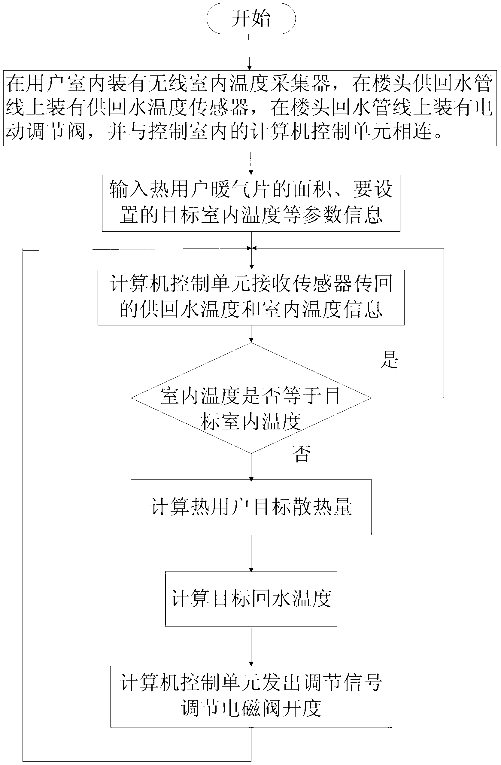
[0029] The computer control unit receives the indoor temperature information sent back by the wireless indoor sensor, and automatically calculates the average indoor temperature of...


PUM


Abstract

The invention discloses a heat supply pipe network hydraulic balance automatic adjustment method. According to the method, a wireless indoor temperature collector, a temperature sensor of return water supplied by a building unit, and an electric adjusting valve on a water return pipeline are connected with a computer control unit, the computer control unit is combined with a target indoor temperature set by an operator, the area of heating radiators in rooms of all users, the outdoor temperature and other parameters for calculation according to acquired data, and therefore the automatic adjusting valve on the water return pipeline can be controlled to perform automatic adjustment, adjustment results are fed back every other time, and conditions of a whole heat supply system can be monitored in real time and adjusted at any time. With the method, labor intensity of workers is reduced, the indoor temperature of the users serves as a target, and the adjustment results are visual and reliable.

Description

technical field [0001] The invention relates to a method for automatically adjusting the hydraulic balance of a heat supply pipe network, in particular to an automatic adjusting method for adjusting the hydraulic balance by studying and changing the return water temperature to adjust the indoor temperature. Background technique [0002] With the further improvement of energy-saving requirements, room temperature compliance requirements and refined heating management requirements, the demand for scientific and rational adjustment of the hydraulic balance of the heating network is becoming more and more intense. The user's indoor temperature is 18±2°C. Due to the distance from the heat source, the newness of the residential buildings, and the insulation effect, the indoor temperature of some users cannot fully meet the heating standards. The imbalance of hydraulic working conditions is common in the heating pipe network, often resulting in overheating at the near end and overc...

Claims


Application Information

Patent Timeline
IPC IPC(8): F24D19/10
Inventor 李克文刘璐王义龙
Owner CHINA UNIV OF PETROLEUM (EAST CHINA)
Learn More