A thermosiphon hot water system for recovery of exhaust energy from household air conditioners

A thermosiphon and hot water system technology, which is applied in the field of waste heat recovery in refrigeration systems, can solve problems such as unsatisfactory waste heat recovery schemes, insignificant waste heat recovery effects, and poor heat exchange effects, and achieve significant waste heat recovery effects, lower temperatures, and installation low cost effect

Active Publication Date: 2017-01-25
BEIJING UNIV OF TECH
View PDF10 Cites 0 Cited by
  • Summary
  • Abstract
  • Description
  • Claims
  • Application Information

AI Technical Summary

Problems solved by technology

However, the biggest disadvantage of these solutions is that the water flows in one direction in the once-through casing heat exchanger, the temperature rise of the water is small, the heat transfer effect is poor, and the waste heat recovery effect is not significant; The time of the water is not synchronized, and it is not ideal to adopt the direct-flow waste heat recovery scheme

Method used


Image

  • A thermosiphon hot water system for recovery of exhaust energy from household air conditioners
  • A thermosiphon hot water system for recovery of exhaust energy from household air conditioners
  • A thermosiphon hot water system for recovery of exhaust energy from household air conditioners

Examples


Embodiment 1

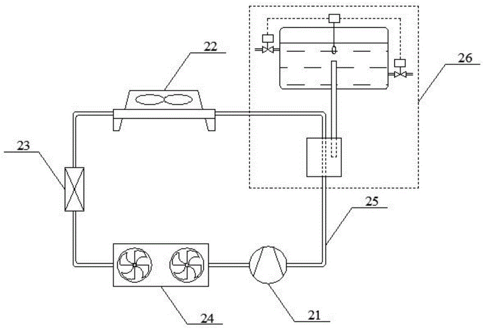
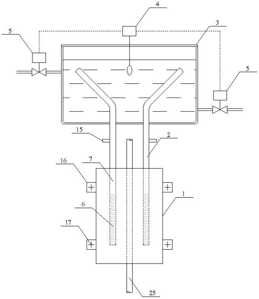
[0024] Such as Figure 1-Figure 5 As shown, a thermosiphon hot water system for recovering exhaust energy of a household air conditioner, the system includes a household air conditioner compressor 21, a compressor exhaust pipe 25, a condenser 22, a throttling device 23, and an evaporator 24 , also includes a thermosiphon hot water system 26 connected on the pipeline between the compressor outlet and the condenser inlet. The compressor 21 continuously sucks the low-pressure and low-temperature refrigerant vapor generated in the evaporator 24, compresses it into high-temperature and high-pressure refrigerant vapor, and transports it to the condenser 22 through the compressor exhaust pipe 25, and undergoes cooling and condensation in the condenser 22. The refrigerant turns into a normal temperature and high pressure liquid, passes through the throttling device 23 into a normal temperature and low pressure refrigerant liquid, and flows into the evaporator 24. The refrigerant liqui...

Embodiment 2

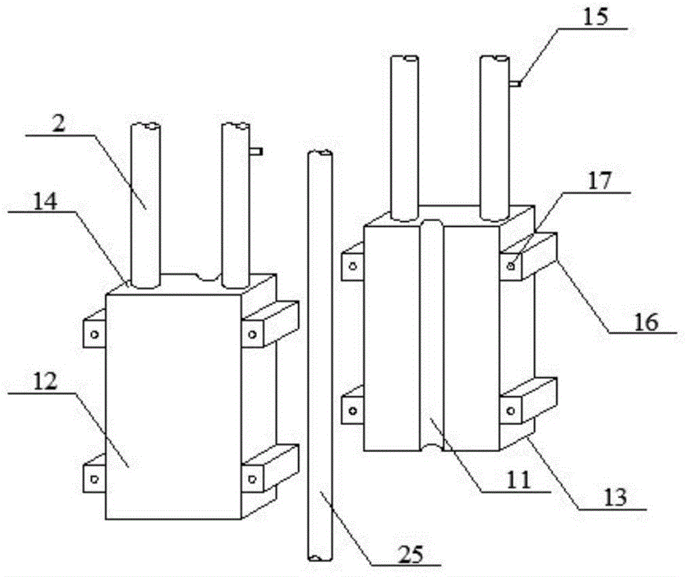
[0036] Figure 6 Shown is the schematic diagram of the thermosiphon hot water system of the second embodiment. In this embodiment, the exhaust pipe 25 of the compressor of the air conditioner is located at a horizontal position.

[0037] The heat absorbing module 1 is a sleeve structure outside the compressor exhaust pipe 25, and the sleeve is made of a metal material (such as copper or aluminum) with good thermal conductivity.

[0038] The lower end cover 13 of the thermosiphon heat exchanger and the upper end cover 14 of the thermosiphon heat exchanger are brazed with the bushing and the exhaust pipe 25 of the compressor. The tube heat exchanger 8 is connected; the thermosiphon 2 includes thermosiphon a2.1, thermosiphon b2.2, thermosiphon c2.3; the gaseous thermosiphon working fluid 6 goes up along the thermosiphon a2.1 and thermosiphon b2.2 To the vertical tube heat exchanger 8, after condensation, it flows back into the casing along the thermosiphon c2.3.

[0039] The p...


PUM


Abstract

The invention relates to a thermosiphon hot water system used for recovering exhaust energy of a domestic air conditioner, and belongs to the technical field of refrigerating system waste heat recovery. Based on the thermotube principle, a large amount of latent heat of vaporization released during phase change of a low-boiling working medium is utilized to obtain high heat exchange efficiency, and waste heat recovery effect is obvious. Temperature of a compressor exhaust pipeline and load of a condenser can be lowered, and performance coefficient of an original refrigerating system is increased; hot water is accumulated in a water tank in a heat accumulation mode, different living needs are met, and the problem that ordinary families use air conditioners and hot water at different time is solved. The thermosiphon hot water system is simple in structure and convenient to mount and dismount, when the domestic air conditioner is modified, the structure of the original refrigerating system is unchanged, and no impact on security and stability of the system is caused. Since no engineering change is made on the original refrigerating system, mounting cost is low, investment payoff period is short, and convenience is brought to popularization and application.

Description

technical field [0001] The invention relates to a thermosiphon hot water system used for recovering exhaust energy of a household air conditioner, and belongs to the technical field of waste heat recovery of refrigeration systems. Background technique [0002] With my country's increasing emphasis on energy conservation and emission reduction and the continuous increase in energy costs, the full use of refrigeration system energy has received more and more attention. The exhaust temperature of the compressor of the household air conditioner is relatively high, generally in the range of 90-120°C. If this part of energy is discharged to the cooling medium, that is, the natural environment through the condenser of the air conditioner, it is undoubtedly a waste of energy. [0003] In order to recover the exhaust energy of the air conditioner compressor, it is more common practice to install a special waste heat recovery heat exchanger on the connecting pipe between the compresso...

Claims


Application Information

Patent Timeline
Patent Type & Authority Patents(China)
IPC IPC(8): F24F12/00
CPCY02B30/56
Inventor 马国远段未周峰
Owner BEIJING UNIV OF TECH
Why Eureka
Try Eureka