Nano-imprinting template, system thereof and imprinting method

A technology of nanoimprinting and templates, which is applied in the direction of nanotechnology, nanotechnology, and nanotechnology for information processing, etc., and can solve the problem of repeated step-by-step thermoplastic nanoimprinting and roll-to-roll thermoplastic nanoimprinting Difficulty and cost increase in printing and template making, inability to complete the nanoimprinting process, etc., to achieve the effects of reducing graphic replication defects, improving process throughput, and broadening the scope of application

Active Publication Date: 2014-07-16
SOUTH UNIVERSITY OF SCIENCE AND TECHNOLOGY OF CHINA
View PDF7 Cites 13 Cited by
  • Summary
  • Abstract
  • Description
  • Claims
  • Application Information

AI Technical Summary

Problems solved by technology

There are some major problems in this design: 1) Due to the slow heat conduction, it takes a long time for the heating and cooling of the large-mass accessory parts, so that the thermoplastic nanoimprinting cycle takes a long time (10 to 20 minutes) , the process throughput is very low
2) It is difficult to achieve repeated step-by-step thermoplastic nanoimprinting and roll-to-roll thermoplastic nanoimprinting
Although the method of increasing the template area can be adopted, this will inevitably lead to a decrease in the uniformity of force and heating, and at the same time, the difficulty and cost of template production will increase accordingly
3) High energy consumption is required for heating large-mass accessory parts, so the existing thermoplastic nanoimprinting consumes high energy consumption
This will cause the equipment to be bulky, complex in structure and high in cost, and at the same time cannot complete some special nanoimprinting processes

Method used


Image

  • Nano-imprinting template, system thereof and imprinting method
  • Nano-imprinting template, system thereof and imprinting method
  • Nano-imprinting template, system thereof and imprinting method

Examples


no. 1 example

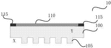
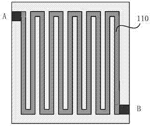
[0077] Figure 1(a)-1(c) It shows a nanoimprint template 10 according to the first embodiment of the present invention, wherein FIG. 1(a) is a front view of the nanoimprint template 10; FIGS. Top view, showing two arrangements of the heating elements.

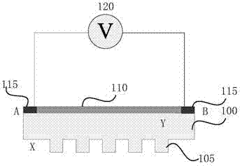
[0078] As shown in FIG. 1( a ), the nanoimprint template 10 includes: a first substrate 100 transparent to ultraviolet light; an imprint pattern structure 105 formed on the first surface of the first substrate (indicated by X in the figure); The heating part 110 is formed on the second surface (indicated by Y in the figure) opposite to the first surface of the first substrate, wherein the heating part 110 is transparent to ultraviolet light; and the first electrode pair 115 is formed on the second surface , for supplying current applied by an external power source to the heating component 110 so that the heating component 110 generates heat.

[0079] Wherein, the first substrate 100 may be made of a UV-transparent double-side...

no. 2 example

[0082] As a modification of the nanoimprint template 10 in the above embodiment, such as image 3 As shown, the nanoimprint template 10 also includes a second substrate 200 transparent to ultraviolet light, wherein the second substrate 200 has the following two functions: one is to fix the first substrate 100, and apply mechanical pressure around the second substrate support frame , can provide the required working pressure for nanoimprinting. Fixation can be done in two ways, mechanical or electromagnetic. Wherein, for electromagnetic fixation, the nanoimprint template further includes a thin film of magnetic material, which is formed on the surface (indicated by W in the figure) opposite to the second surface of the first substrate of the second substrate 200, and is used to heat the component when the current passes through it. 110 to attract the first substrate 100 and the second substrate 200 by electromagnetic force when forming an electromagnetic field. Another functi...

no. 3 example

[0086]The present invention also provides a nanoimprint system, including the nanoimprint template 10 as described in the first embodiment or the second embodiment and a substrate carrying platform 30 for carrying a substrate 20 to be imprinted, such as Figure 4 shown. Notice, Figure 4 Shown in is the case of including the nanoimprint template 10 in the second embodiment (ie, having the second substrate 200 ).

[0087] Different from traditional nanoimprinting using water cooling or air cooling, the present invention can install a thermoelectric cooler on the substrate carrying platform 20 to rapidly cool the substrate and precisely control the cooling temperature. In addition, the use of thermoelectric coolers can generate temperatures lower than ambient, so they can be used for embossing adhesives whose curing temperature is lower than room temperature. Specifically, the thermoelectric cooler includes a thermoelectric cooling control circuit (not shown in the figure) and...


PUM


Abstract

The invention discloses a nano-imprinting template, a system thereof, and an imprinting method. The nano-imprinting template includes: a first substrate transparent to ultraviolet light, an imprinting pattern structure formed on the first surface of the first substrate, a heating part which is formed on the second surface of the first substrate opposite to the first surface and is transparent to the ultraviolet light, and a first electrode pair formed on the second surface and used for supplying a current applied by an external power supply to the heating part in order to make the heating part generate heat. The nano-imprinting template and the system seamlessly fuse an ultraviolet curable nano-imprinting technology with a thermoplastic nano-imprinting technology, and have the advantages of small size, low cost, simple process and the like. When the template and the system are utilized to carry out thermoplastic nano-imprinting, a large area of micro-nano figures can be copied; and when the template and the system are utilized to carry out ultraviolet curable nano-imprinting, the technologic throughput is improved, and figure copying defects are reduced.

Description

technical field [0001] The invention relates to the technical field of nanoimprinting, in particular to a nanoimprinting template, system and imprinting method. Background technique [0002] Ultra-high-precision semiconductor surface patterning technology is the core and cutting-edge technology in microelectronics technology. At present, the mainstream surface patterning technology used in large-scale manufacturing of integrated circuits is 193nm immersion lithography technology and secondary patterning technology. With the continuous reduction of chip feature size in the future, the existing lithography technology can no longer meet the requirements of the next-generation 22nm half-cycle dynamic random access memory and 16nm half-cycle flash memory. [0003] Nanoimprint technology is a micro-nano manufacturing technology that has developed rapidly in the world in recent years. It has attracted the attention of academia and industry for its ultra-high pattern accuracy (sub-...

Claims


Application Information

Patent Timeline
Patent Type & Authority Applications(China)
IPC IPC(8): G03F7/00H01L21/67B82Y10/00
CPCG03F7/0002B29C59/002B29C59/022B29C59/026B29K2701/12B29L2031/34
Inventor 程鑫崔德虎李自平明静张众
Owner SOUTH UNIVERSITY OF SCIENCE AND TECHNOLOGY OF CHINA
Why Eureka
Try Eureka